Inkjet system, method of making this system, and use of said system

a technology of inkjet printers and inkjet printers, applied in the field of inkjet printers, can solve problems such as damage to printers, and achieve the effect of simple electronics and adequate tracing of disturbances

Inactive Publication Date: 2010-04-27
OCE TECH
View PDF6 Cites 5 Cited by
  • Summary
  • Abstract
  • Description
  • Claims
  • Application Information

AI Technical Summary

Benefits of technology

[0008]The advantage of the present invention is that analysis of the signal generated by the actuator can be effected with very simple electronics, and yet an adequate tracing of disturbances can be found. A disturbance in the context of the present invention is an irregularity in the system regarded as unacceptable. This can, for example, be the case if the irregularity can result in a print artefact visible to the human eye in the printed image, or if the irregularity can result in damage to the printer. The unacceptability of an irregularity may vary from one application to another.
[0009]In one embodiment, a natural frequency of the system substantially corresponds to a natural frequency of an air bubble of a size such that it noticeably influences the ejection of ink drops. It is generally known that one or more air bubbles may be located in an ink duct. On the one hand, they can be present in the ink itself and possibly even grow in the ink duct, on the other hand they can also form in the ink duct, particularly because of negative pressures which can be generated in the ink duct (cavitation). However, many of these air bubbles are not a disturbance in the sense of the present invention. They are often so small that they have no noticeable influence on the jetting process and disappear automatically after a specific time or after a number of energizations of the actuator. However, a critical value can be determined for an air bubble at which it just will noticeably influence the ejection of the ink drops. In this embodiment, the natural frequency of an air bubble having this critical value just falls in the window around the natural frequency of the system. In this way, air bubbles which have a size below the critical value can simply be disregarded. As soon as a bubble becomes so great that it can be regarded as a disturbance, it can simply be rendered visible in the signal generated by the actuator.
[0010]In another embodiment, the measuring circuit comprises a mixer in order to mix with the signal a frequency equal to the natural frequency of the system. The advantage of this embodiment is that the presence of an air bubble with a critical value can be noted very simply, for example using a low-pass filter. By mixing (multiplying) with the natural frequency of the system (which frequency substantially corresponds to that of the disturbance), the disturbance will be visible at a frequency substantially equal to zero. This offers the possibility of detecting the disturbance by the use of very simple electronics.
[0011]The present invention also covers a method of making an inkjet system comprising forming an ink chamber with a nozzle for the ejection of ink drops from the chamber, which ink chamber is operatively connected to a piezoelectric actuator, connecting the actuator to a measuring circuit, wherein the system is so configured that a natural frequency of the system is substantially equal to a natural frequency of a disturbance in the system. In addition, the invention also relates to application of the above-described system to the formation of an image on a receiving material.

Problems solved by technology

This can, for example, be the case if the irregularity can result in a print artefact visible to the human eye in the printed image, or if the irregularity can result in damage to the printer.

Method used


Image

  • Inkjet system, method of making this system, and use of said system
  • Inkjet system, method of making this system, and use of said system
  • Inkjet system, method of making this system, and use of said system

Examples


Embodiment Construction

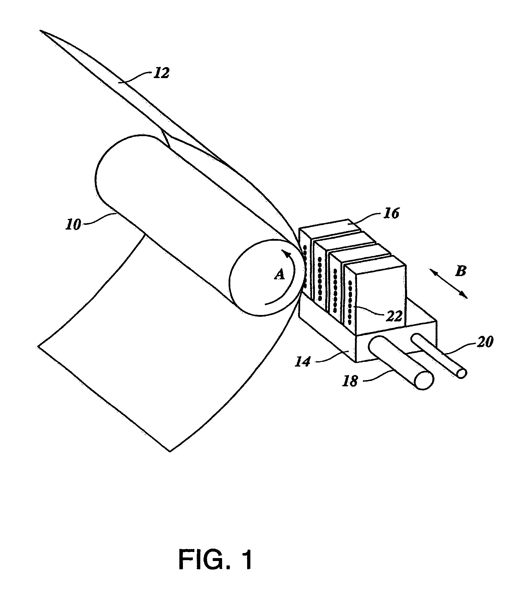
[0020]FIG. 1 diagrammatically illustrates an inkjet printer. In this embodiment, the printer comprises a roller 10 to support a receiving medium 12 and guided along the four printheads 16. The roller 10 is rotatable about its axis as indicated by arrow A. A carriage 14 carries the four printheads 16, one for each of the colors cyan, magenta, yellow and black, and can be moved in reciprocation in a direction indicated by the double arrow B, parallel to the roller 10. In this way the printheads 16 can scan the receiving medium 12. The carriage 14 is guided over rods 18 and 20 and is driven by suitable means (not shown).

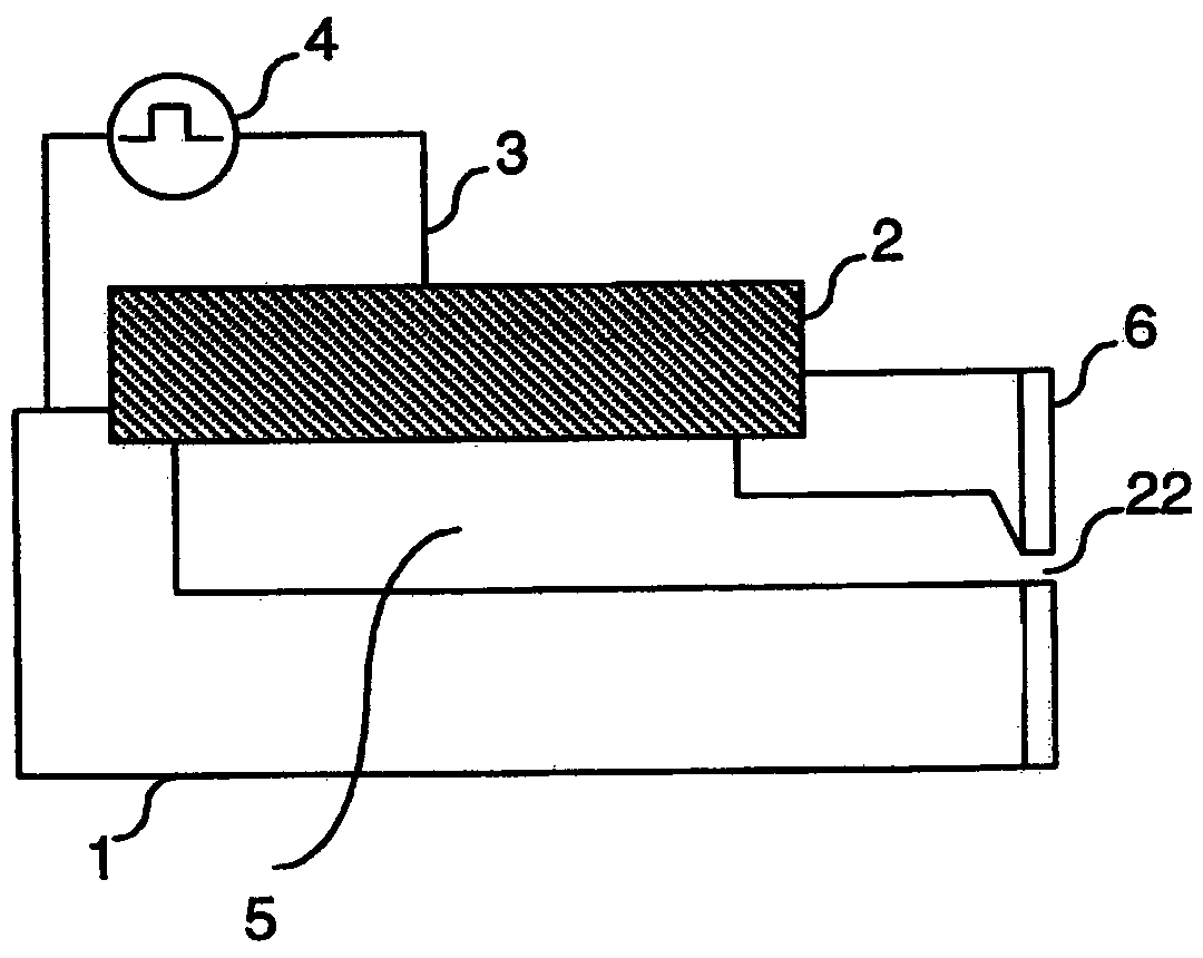
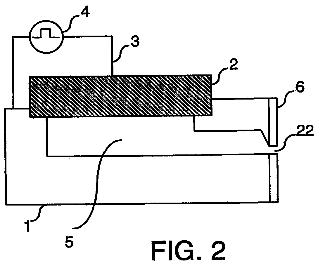
[0021]In the embodiment as shown in the drawing, each printhead 16 comprises eight ink chambers, each with its own nozzle 22, which form an imaginary line perpendicular to the axis of the roller 10. In a practical embodiment of a printing device, the number of ink chambers per printhead 16 is many times greater. Each ink chamber is provided with a piezoelectric actuator...


PUM


Abstract

An inkjet system including a printhead with an ink-fillable chamber operatively connected to a piezoelectric actuator and provided with a nozzle for the ejection of ink drops in response to the energization of the actuator, which actuator is connected to a measuring circuit for measuring an electrical signal generated by the actuator in response to the deformation thereof, wherein the system is configured such that a natural frequency of said system corresponds substantially to a natural frequency of a disturbance in the system.

Description

[0001]This Nonprovisional application claims priority under 35 U.S.C. §119(a) on Patent Application No(s). 1026486 filed in The Netherlands on Jun. 23, 2004, the entire contents of which are hereby incorporated by reference.BACKGROUND OF THE INVENTION[0002]The present invention relates to an inkjet system including a printhead comprising an ink-fillable chamber operatively connected to a piezoelectric actuator and provided with a nozzle for the ejection of ink drops in response to the energization of the actuator, said actuator being connected to a measuring circuit for measuring an electric signal generated by the actuator in response to the deformation thereof. The present invention also relates to a method of making such a system and use of said system in forming an image on a receiving material.[0003]A system of this kind is known from European Application EP 1 013 453. This system forms part of an inkjet printer with which receiving materials can be printed. The known system is...

Claims


Application Information

Patent Timeline
Patent Type & Authority Patents(United States)
IPC IPC(8): B41J2/05B41J29/393B41J2/045B41J2/125B41J2/19
CPCB41J2/04555B41J2/04581B41J2/19B41J2/125B41J2002/14354
Inventor GRONINGER, MARK A.VAN DEN BERG, MARCUS J.WIJSHOFF, HERMANUS M. A.
Owner OCE TECH
Why Eureka
Try Eureka