
Optical system for measurement of orientation and position comprising a point source, central mask, photosensitive matrix sensor and corner cube

a technology of optical system and orientation, applied in the field of optical devices, can solve the problems of large loss of light flux, heavy and expensive double image acquisition electronics, etc., and achieve the effects of improving the photometric yield of the assembly, improving the accuracy of measurement, and simplifying the fixed devi

Active Publication Date: 2015-08-18
THALES SA
View PDF12 Cites 1 Cited by
  • Summary
  • Abstract
  • Description
  • Claims
  • Application Information

AI Technical Summary

Benefits of technology

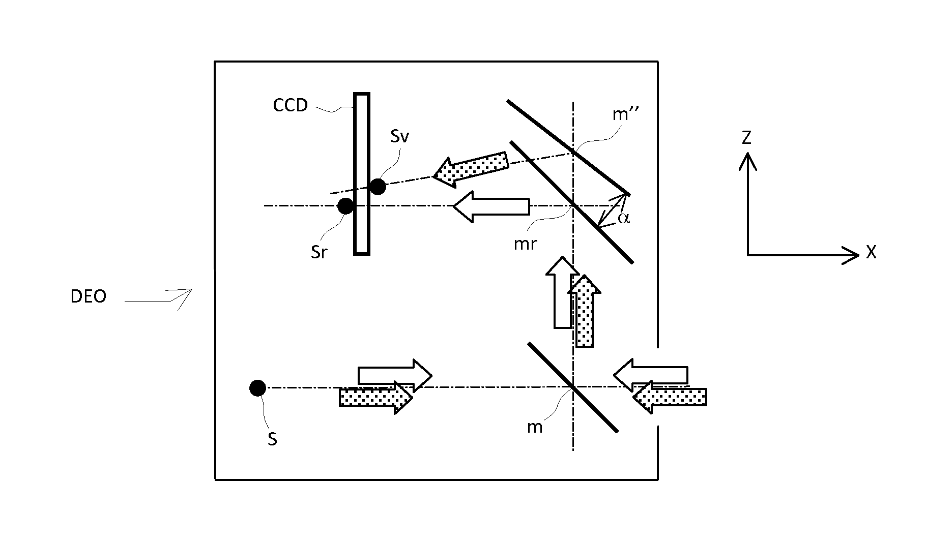
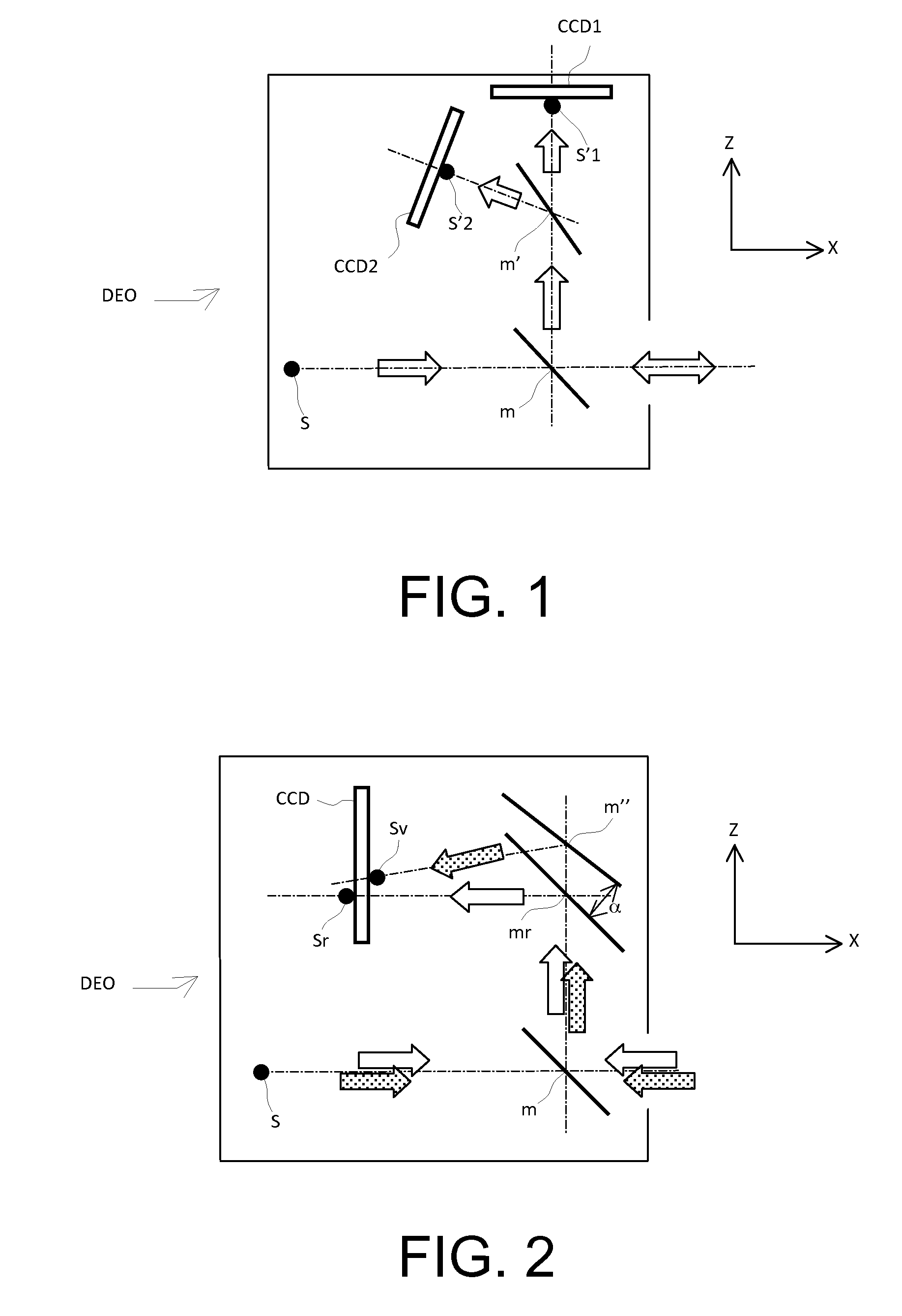
The fixed optoelectronic device in this patent improves the measurement precision of an optical system by using a known angle between the direction of the contour of the diaphragm or mask and the direction of the contour of the screen. The device is also more compact and requires simpler electronics than a system with two sensors. Additionally, the device has an optical system that forms an image of the source onto the optical element.

Problems solved by technology

It is therefore bulky and requires double image acquisition electronics;The light source emits in an angular aperture wide enough to cover all the possible positions of the reflector.
A very large part of the light flux is therefore permanently lost, since it does not reach the reflector.

Method used


Image

  • Optical system for measurement of orientation and position comprising a point source, central mask, photosensitive matrix sensor and corner cube
  • Optical system for measurement of orientation and position comprising a point source, central mask, photosensitive matrix sensor and corner cube
  • Optical system for measurement of orientation and position comprising a point source, central mask, photosensitive matrix sensor and corner cube

Examples


first embodiment

[0068]A first embodiment is represented in the cross-sectional views of FIGS. 15 and 16. The electro-optical device essentially comprises a point source S, a matrix sensor CM, and a mirror m comprising a transparent central opening EC1. In a first variant, the source is arranged behind this central opening. The radiation emitted by the source S passes through this opening EC1 and is reflected by the corner cube (not represented in FIG. 15). The peripheral part of the luminous contour is reflected by the mirror m towards the matrix sensor CM, while its central part is lost. A luminous contour with a dark zone is obtained. The opening EC1 of the mirror therefore corresponds to the obturating optical element. It may be reduced to a simple hole or have a more complex geometrical shape, as has been seen. A mask may be added at the source S so that the source does not directly illuminate the matrix sensor CM.

[0069]In a simple variant, which is represented in FIG. 16, focusing optics L whi...

second embodiment

[0071]the electro-optical device according to the invention is represented in FIG. 18. This FIG. 18 comprises a side view and a front view of the device. In this case, the electro-optical device essentially comprises a point source S, a matrix sensor CM, and a transparent plate LA comprising an opaque central screen EC3. The point source S is fixed in the vicinity of the centre of the opaque central screen. The central screen EC3 comprises an extension in the shape of a bar B. making it possible to mask the cabling of the point source. Here again, a luminous contour with a dark zone is obtained on the sensor CM, as can be seen in FIG. 19, which represents the image obtained on the matrix sensor. In the case of FIGS. 18 and 19, the central screen has a rectangular shape. The image B′ of the bar is easily identifiable, and in no way interferes with identification of the sides of the shade.

[0072]In an alternative embodiment, which is represented in FIG. 20, focusing optics L which form...


PUM


Abstract

The general field of the invention is that of systems for detecting the posture of a mobile object. The systems according to the invention comprise a fixed electro-optical device comprising an emission source and a photosensitive sensor. The optical corner cube is arranged on the mobile object. The entry face of the corner cube has a predetermined geometry, the light coming from the source and reflected back by the corner cube forming a luminous contour on the matrix sensor. The fixed electro-optical device comprises an optical element with a known shape and location, which is placed in the vicinity of the said source and is arranged so as to form a dark zone in the central part of the luminous contour. The detection system comprises analysis means determining the position and the orientation of the mobile object from knowledge of the vanishing points of the luminous contour and the position and shape of the dark zone.

Description

BACKGROUND OF THE INVENTION[0001]1. Field of the Invention[0002]The field of the invention is that of optical devices making it possible to measure the orientation of an object in space without contact. There are various possible fields of application, but the main application is that of detecting the posture of the helmet of an aircraft pilot, thus making it possible to project an image into his visor in exact superposition on the exterior landscape or to slave various systems of the aircraft under his view. The precision sought in such systems is of the order of one milliradian.[0003]2. Description of the Prior Art[0004]There are various optical techniques for measuring the orientation of a helmet. Generally, conspicuous elements are installed on the helmet, and these are located by an optical emission and reception system. The positions of the images of these conspicuous elements make it possible to determine the position and the orientation of the helmet by calculation.[0005]To ...

Claims


Application Information

Patent Timeline
IPC IPC(8): G01B11/00G01S17/87G01S5/16F41G3/22G01S17/875
CPCG01S17/875G01S5/16G01B11/002F41G3/225
Inventor BARBIER, BRUNOPOTIN, LAURENTROUZES, SIEGFRIED
Owner THALES SA
Learn More