Oil port position sensing device

a sensing device and oil port technology, applied in the field of sensors, can solve the problems of not providing information, unable to correlate with the sensing device, and time-consuming process, and achieve the effect of efficient orienting the oil por

Active Publication Date: 2016-09-06
CHECKFLUID
View PDF17 Cites 1 Cited by
  • Summary
  • Abstract
  • Description
  • Claims
  • Application Information

AI Technical Summary

Benefits of technology

[0024]In use, the apparatus is mounted on the rotating element so that the indicium indicates the direction of the oil port on the rotating element. Where more than one indicium is present, the apparatus is mounted on the rotating element so that the indicium associated with the desired service action is the one indicating the direction of the oil port. The apparatus may be designed to be mounted at any location on the rotating element, but it is preferable to design the apparatus to be mounted on the rotating element so that is centered on the axis of rotation of the rotating element. In this way the apparatus is suitable to be used with any diameter rotating element and greatly simplifies the electronics associated with the sensor, transmitter and receiver.
[0027]Advantageously, only a single person is needed to put a vehicle, and hence the oil port, in the correct position for the desired service action. The invention allows a single person to efficiently orient the oil port without needing to leave the vehicle. A vehicle operator will know when to stop the vehicle without needing to get in and out of the vehicle to check on the position of the oil port. Further, because the apparatus is portable, a service person can take the apparatus from location to location so that there is no need for separate apparatuses for each vehicle.

Problems solved by technology

If only one person is available, the process is time consuming.
However, the sensor does not provide information about the position of the oil port on a rotating wheel or track, nor can the sensing device correlate oil port position to the orientation of the sensing device.

Method used


Image

  • Oil port position sensing device
  • Oil port position sensing device
  • Oil port position sensing device

Examples


Embodiment Construction

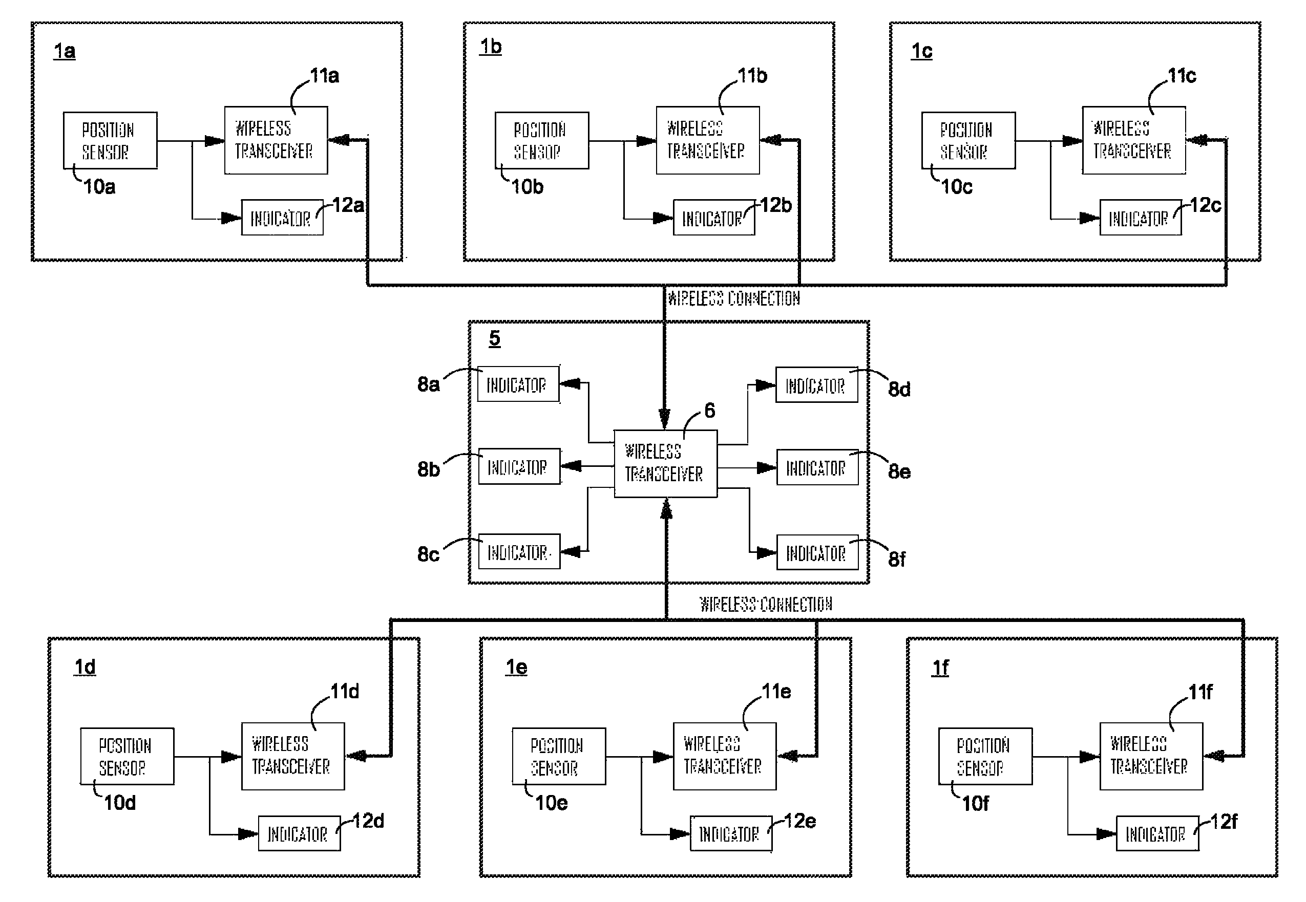
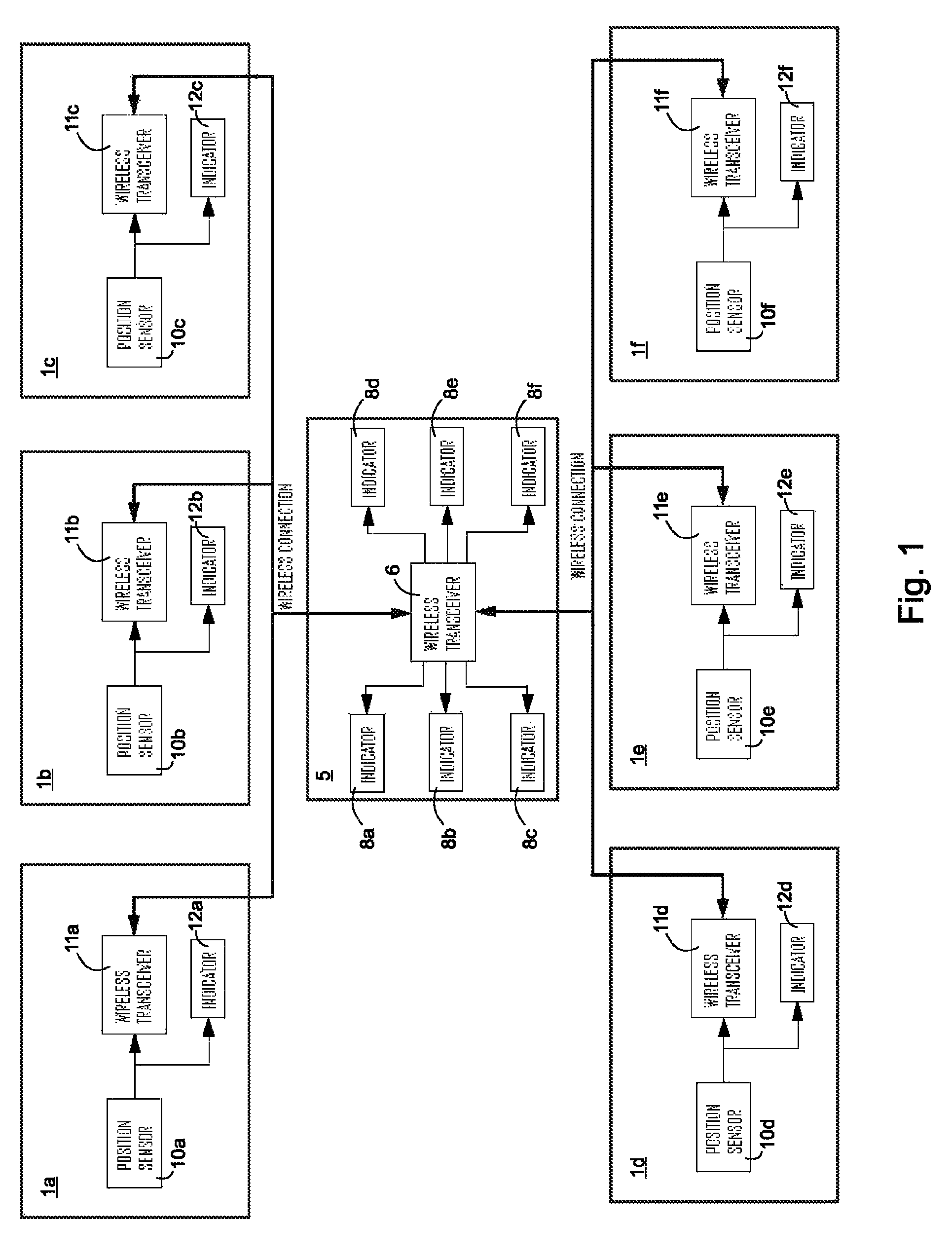
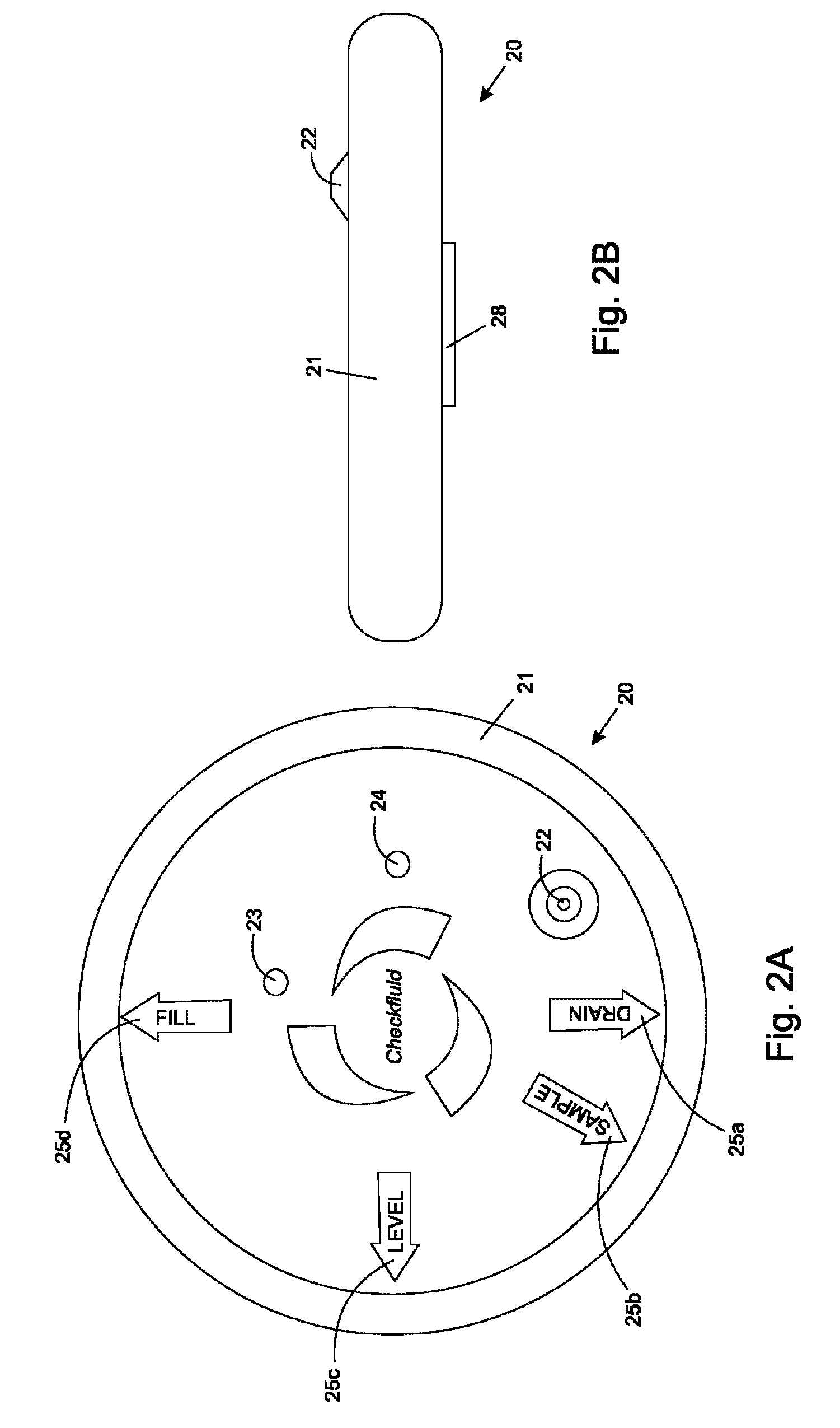
[0034]In one embodiment, the invention pertains to an apparatus that senses the position of a rotating oil port on a heavy vehicle wheel or track. According to one aspect of the invention, an orientation sensor such as a 2- or 3-axis accelerometer and associated electronics is enclosed in a protective housing that is temporarily mounted on a front face of the wheel or track via a magnet or other means. On the orientation sensor housing are several indicators. By rotating the orientation sensor, the user can choose which oil port orientation is desired. Some of the indicators include but are not limited to oil port fill position (oil port is at the top of the wheel), drain position (oil port at bottom), level check position (oil port at mid-range) and oil sampling position (oil port between bottom location and mid-range location). In one aspect, the orientation sensor housing contains a light that is illuminated when the oil port reaches the desired position. Furthermore a receiver u...


PUM


Abstract

A portable apparatus for sensing position of an oil port on a rotating element (e.g. the wheel or track of a heavy vehicle) has a position sensor in electrical communication with a wireless transmitter. The wireless transmitter is configured to receive signals from the position sensor and to send signals to a wireless receiver. The apparatus further has a mounting structure (e.g. a magnet) for temporarily mounting the apparatus on the rotating element. An indicium on the apparatus associated with a desired service action to be performed on the rotating element correlates an angular position of the oil port to a pre-determined reference position of the position sensor, the angular position of the oil port being a correct position for performing the desired service action. In use, the apparatus is mounted on the rotating element so that the indicium points at the oil port and then the rotating element is rotated until the receiver indicates that the oil port is in the correct position.

Description

CROSS-REFERENCE TO RELATED APPLICATIONS[0001]This application claims the benefit of U.S. Patent Application 61 / 819,449, filed May 3, 2013, the entirety of which is incorporated herein by reference.FIELD OF THE INVENTION[0002]The present invention relates to sensors, particularly to sensors for determining position of an oil port on a rotating element of a vehicle.BACKGROUND OF THE INVENTION[0003]Many types of heavy equipment utilize final drives, differentials and transmissions. In some cases, the only way to access the oil in the transmission and final drive is through a single oil port that is located on the equipment's wheel or track. Depending on the service action that is required, the oil port must be positioned differently. To fill the oil, the oil port must be located at the top of the wheel or track. To drain the oil, the oil port must be located at the bottom of the wheel. Oil sampling and level checking also require the oil port to be positioned differently in relation to...

Claims


Application Information

Patent Timeline
Patent Type & Authority Patents(United States)
IPC IPC(8): E21B47/09G01D3/10G01D11/30
CPCG01D11/30G01D3/10
Inventor HALL, MICHAEL BERNARD
Owner CHECKFLUID
Why Eureka
Try Eureka