Regulating body for a wristwatch

a technology of regulating body and wristwatch, which is applied in the direction of electromechanical clocks, ac motor stoppers, instruments, etc., can solve the problems of inefficient use of available energy, difficult circuit adjustment, and limited precision that can be achieved by means of a regulator member of this type, so as to reduce increase the number of coils, and control the intensity of braking

Inactive Publication Date: 2015-11-05
RICHEMONT INT
View PDF5 Cites 2 Cited by
  • Summary
  • Abstract
  • Description
  • Claims
  • Application Information

AI Technical Summary

Benefits of technology

[0021]In one embodiment, only N coils are used for controlling the variable braking applied to the rotor, whilst the other M coils are not used for braking, or in any case for controlling the braking. This solution has the advantage of braking only on N coils and of permanently keeping at least M coils for powering the electronic regulating circuit, even in the event of maximum braking. It is thus possible to avoid sudden voltage drops due to the simultaneous short-circuiting of all coils, to simplify the electronics and / or to achieve greater operating flexibility by enabling, for example, different braking strategies to be used.
[0053]The duration T1+T2 of the cycles can be reduced when the watch runs in chronograph mode, in order to enable an accurate measurement of brief durations.

Problems solved by technology

The precision that can be achieved by means of a regulator member of this type, however, is limited.
Due to their sensitivity to errors and phase variations of the components, these circuits are difficult to adjust.
The sudden accelerations and decelerations applied result in an inefficient use of the available energy.
Braking circuits known in this type of application, however, have the disadvantage of reducing the voltage available at the terminals of the stator coils during braking.
The problem is particularly crucial when the microgenerator is sized to turn too quickly and has to be braked and regulated permanently.
In this case, the braking permanently reduces the voltage generated and it becomes difficult to guarantee sufficient voltage for powering the electronic circuit for regulating the running of the generator.
This results in the paradoxical situation that when the generator turns too fast, by reason of an abundance of mechanical energy for making the rewinding mass oscillate, the electric voltage available for powering the electric circuit diminishes, to the point where this circuit sometimes risks stopping.
The switching of the rectifier's operation mode, however, causes sudden variations of the braking torque applied to the generator, which is unfavorable to an efficient use of the available energy.

Method used


Image

  • Regulating body for a wristwatch
  • Regulating body for a wristwatch
  • Regulating body for a wristwatch

Examples


Embodiment Construction

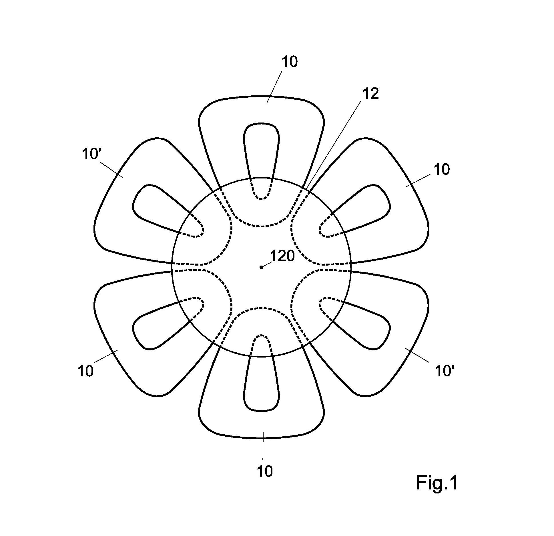
[0064]The regulating member for a wristwatch comprises a generator illustrated diagrammatically in FIG. 1. The generator of this example comprises a rotor 12 mounted on the arbor 120 of a pinion or of a wheel (not represented) connected to the geartrain of a mechanical movement (not represented) whose speed it regulates. The rotor 12 comprises a plate with magnetic portions, not represented, for example discrete magnets or magnetized portions, that generate a rotating magnetic field when the rotor is driven in rotation by the geartrain of a mechanical movement. In one variant, it is also possible to provide a rotor with several plates, for example a rotor with two coaxial plates superimposed one above the other.

[0065]The generator further comprises a stator with coils 10, 10′ placed so that the rotating magnetic field generated by the rotation of the rotor 12 induces induced voltages in the coils. The figure illustrates a construction with six coils spread angularly in a roughly reg...


PUM


Abstract

Regulating body for a wristwatch, comprising: a generator provided with a rotor and a stator with M+N coils, M being a whole number higher than, or equal to, 1; and an electronic regulating circuit having a first load impedance with an adjustable value for adjusting the current in N of said M+N coils, and therefore the rotational speed of the rotor. Only a limited number of coils is therefore used for the braking, the other coils continuing to supply the electronic regulating circuit.

Description

TECHNICAL FIELD[0001]The present invention concerns a regulating member for a wristwatch, notably an electronic regulating member for a mechanical wristwatch.STATE OF THE ART[0002]Mechanical wristwatches are usually regulated by means of an assembly comprising a spiral and a balance. The precision that can be achieved by means of a regulator member of this type, however, is limited.[0003]Electronic watches are usually regulated by means of a quartz oscillator. The accuracy that can be achieved is greater than that of mechanical movements, but these watches usually require a battery that needs to be replaced periodically.[0004]In order to overcome these drawbacks, the state of the art also knows watches that comprise a mechanical movement regulated by an electronic circuit with a quartz oscillator. The energy required for the electronic circuit is supplied by a microgenerator driven by the movement.[0005]Thus, CH-A-597636 (Ebauches S. A.) proposes a mechanical movement with a barrel ...

Claims


Application Information

Patent Timeline
Patent Type & Authority Applications(United States)
IPC IPC(8): G04C3/16
CPCG04C3/165G04C3/064G04C10/00H02P3/22H02P8/16
Inventor TAGHEZOUT, DAHOMEIER, WILLYMICHALET, ALEXANDRESTRAUMANN, KURT
Owner RICHEMONT INT
Why Eureka
Try Eureka