Optical recording medium

a technology of optical recording medium and recording medium, which is applied in the field of optical recording medium, can solve the problems of long-term storage of data recorded in optical recording medium, and achieve the effects of high recording density, high transmittance velocity, and high recording sensibility and contras

Inactive Publication Date: 2010-04-27
LG ELECTRONICS INC
View PDF10 Cites 4 Cited by
  • Summary
  • Abstract
  • Description
  • Claims
  • Application Information

AI Technical Summary

Benefits of technology

[0016]Another object of the present invention is to provide an optical recording medium that has high recording sensibility and big contrast between recording mark and space as well as satisfies characteristic of BD.
[0017]Another object of the present invention is to provide an optical recording medium that has superior stability of recording mark and superior recording characteristic of jitter as well as satisfies characteristic of BD.
[0018]Another object of the present invention is to provide an optical recording medium which the laser power necessary for making recording mark is low.
[0021]The optical recording medium of the present invention may provide high recording density and high transmittance velocity suitable for BD system by combining elements of the recording layer material.
[0022]Also, the optical recording medium of the present invention may provide high recording sensibility and contrast between recording mark and space as well as record data in high density.
[0023]Moreover, in the optical recording medium of the present invention, laser power necessary for making recording mark may be low. Further, the optical recording medium of the present invention may provide very stable recording mark and superior recording characteristic.

Problems solved by technology

Only, in case of using organic material as the recording layer material, a problem may be occurred in long term storage of data recorded in the optical recording medium.

Method used


Image

  • Optical recording medium
  • Optical recording medium
  • Optical recording medium

Examples


first embodiment

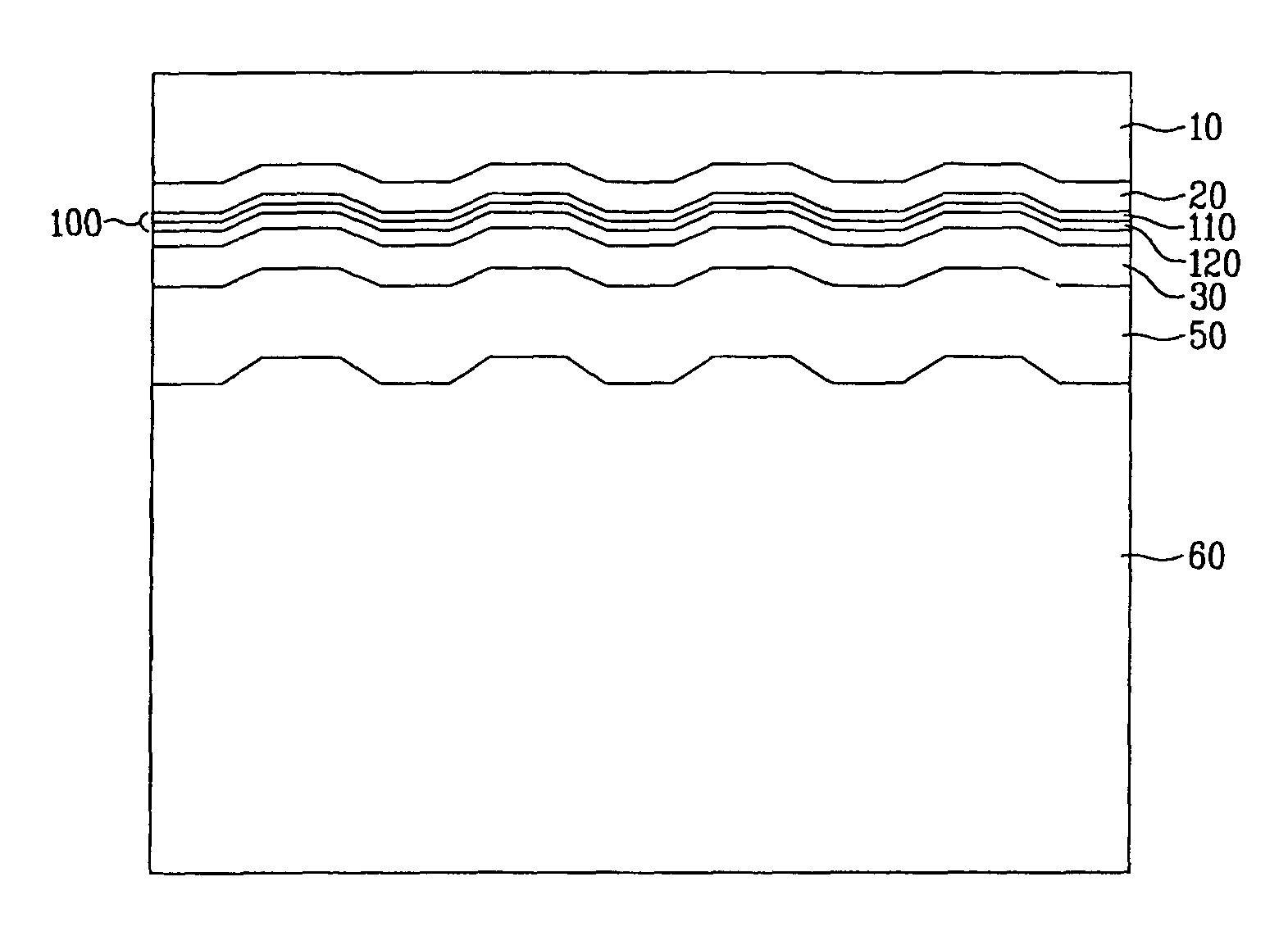
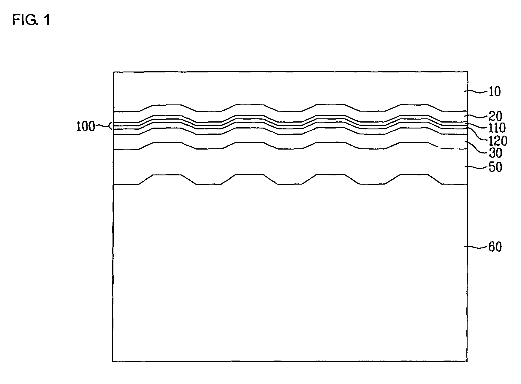
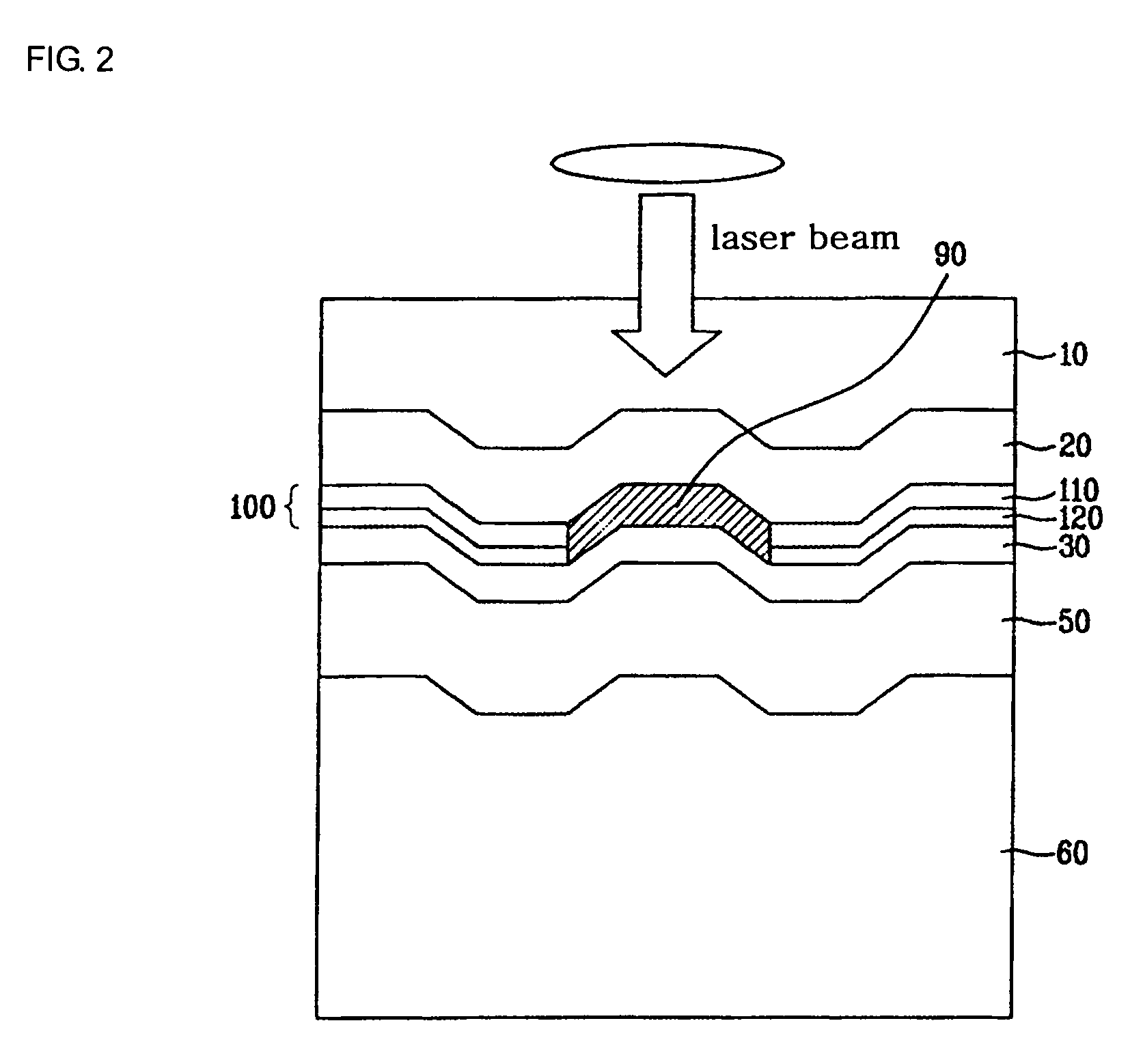
[0043]FIG. 1 is a sectional view illustrating the structure of the optical recording medium according to the present invention. FIG. 2 is a sectional view illustrating one form of generated record mark in case of performing land recording to the optical recording medium of FIG. 1. And, FIG. 3 is a sectional view illustrating one form of generated record mark in case of performing groove recording to the optical recording medium of FIG. 1.

[0044]In FIG. 1, the optical recording medium of the present invention includes a substrate 60, a reflective layer 50 and an information recording layer 100. It is desirable to further include an optical transmittance layer 10 and a dielectric layer 20, 30.

[0045]The substrate 60 plays a role to support a physical form of the optical recording medium. As material of the substrate 60, ceramic, glass, resin, etc. are generally used, and polycarbonate resin is preferable.

[0046]The reflective layer 50 is deposited on the substrate 60, reflects laser beam...

second embodiment

[0061]FIG. 4 is a sectional view illustrating one form of generated record mark in case a recording sensibility promotion layer is included in the optical recording medium according to the present invention.

[0062]In FIG. 4, the recording sensibility promotion layer 70 may be laminated around or inside the information recording layer 100 in the optical recording medium according to the second embodiment of the present invention.

[0063]It is desirable that the recording sensibility promotion layer 70 contains at least one element selected from the group consisting of Sn, Zn, Pb, Bi, TI, Te, Se, S, Al, Ga, Ge, Cd, I, and In. These elements react earlier than material of the information recording layer 100 because their melting point is low when the laser beam is irradiated, and latent heat generated by state change at the time of reaction may be partially supplied for the heat necessary for reaction of the first recording layer 110 or the second recording layer 120.

[0064]Thus, in case t...

third embodiment

[0068]FIG. 5 is a sectional view illustrating one form of generated record mark in case the first recording layer and the second recording layer are laminated in turn to the information recording layer of the optical recording medium according to the present invention.

[0069]In FIG. 5, the optical recording medium according to the third embodiment of the present invention includes one or more first recording layers 110, 112, and one or more second recording layers 120 in the information recording layer 100. The first recording layers 110, 112 and the second recording layers 120 are laminated in turn so that their contact sides become two or more.

[0070]In such lamination, the reaction area between the first recording layer 110, 112 and the second recording layer 120 is increased so that the recording mark 90 is easily generated in the thickness direction of the optical recording medium.


PUM

PropertyMeasurementUnit
thicknessaaaaaaaaaa
thicknessaaaaaaaaaa
linear velocityaaaaaaaaaa

Abstract

The optical recording medium according to one embodiment of the present invention includes a substrate, a reflective layer located on the upper side of the substrate and reflecting an incident laser beam, and an information recording layer located on the reflective layer. The information recording layer includes a first recording layer containing a compound in the form of AXB1-X (0.8≦X≦0.9), wherein A is Ag and B is Sb and Te, and a second recording layer containing at least one element selected from the group consisting of Si, Sn, Sb and Ge. The laser beam is irradiated on the first recording layer prior to the second recording layer. Therefore, the optical recording medium of the present invention may provide high recording density and transmittance velocity suitable for BLU-RAY DISC system.

Description

BACKGROUND OF THE INVENTION[0001]1. Field of the Invention[0002]The present invention relates to an optical recording medium. In particular, the present invention relates to a recordable optical recording medium that can densely record data as well as has high recording stability.[0003]2. Description of the Related Art[0004]With the advent of multimedia age comprehensively dealing with video signal including moving picture and stop picture, audio signal, and computer data information, package media including all kinds of discs like CD and DVD have been widely used. Recently, there have been active efforts to apply an optical recording medium to the recording media of mobile phone, digital camera, broadcasting, and movie.[0005]The optical recording medium is divided into read-only memory (ROM) optical recording medium, recordable optical recording medium capable of recording information only once, and rewritable optical recording medium capable of writing, reading, and deleting infor...

Claims


Application Information

Patent Timeline
Patent Type & Authority Patents(United States)
IPC IPC(8): B32B3/02G11B7/243G11B7/257
CPCG11B7/243G11B7/24038Y10S428/913Y10S430/146
Inventor LEE, KWANG LYUL
Owner LG ELECTRONICS INC
Why Eureka
Try Eureka