Photonic touch screen apparatus and method of use

a touch screen and touch screen technology, applied in the field of display screen input devices, can solve the problems of impracticality of devices, slow mouse or light pen placement, and difficulty in short placement of mouse or light pen for high-speed applications

Inactive Publication Date: 2010-04-27
EIKMAN ADAM
View PDF19 Cites 126 Cited by
  • Summary
  • Abstract
  • Description
  • Claims
  • Application Information

AI Technical Summary

Problems solved by technology

In many instances, such as self serve ticket vending terminals and automated teller machines, these devices are impractical and direct tactile contact with the computer screen is the preferred input mode.
The mouse or the light pen is precise but slow, translating the dexterity of the human hand to tedious positioning of a single indicator icon on a screen.
The mouse or light pen is difficult to place briefly for high-speed applications such as music composition, game playing, and free hand drawing.
A drawback of the sensing sheets technologies is that the sheets are necessarily less hard and less durable than the glass or other clear panel of the underlying display.
Hence these sheets are prone to wear and damage.
Additional disadvantages of current touch screen technology are the high cost of large screens, degradation in screen clarity and excessive bulk that limits the ergonomic adjustment for access to large touch screens.
The touch screens in current use are scalable to large size only with substantial increase in cost and bulk, and constrained in the number of simultaneous input positions that can be entered simultaneously, typically one.
This optical phenomenon is well known, but to date, efficient, robust devices have not been developed to exploit FTIR to produce an effective touch screen input device.

Method used


Image

  • Photonic touch screen apparatus and method of use
  • Photonic touch screen apparatus and method of use
  • Photonic touch screen apparatus and method of use

Examples


Embodiment Construction

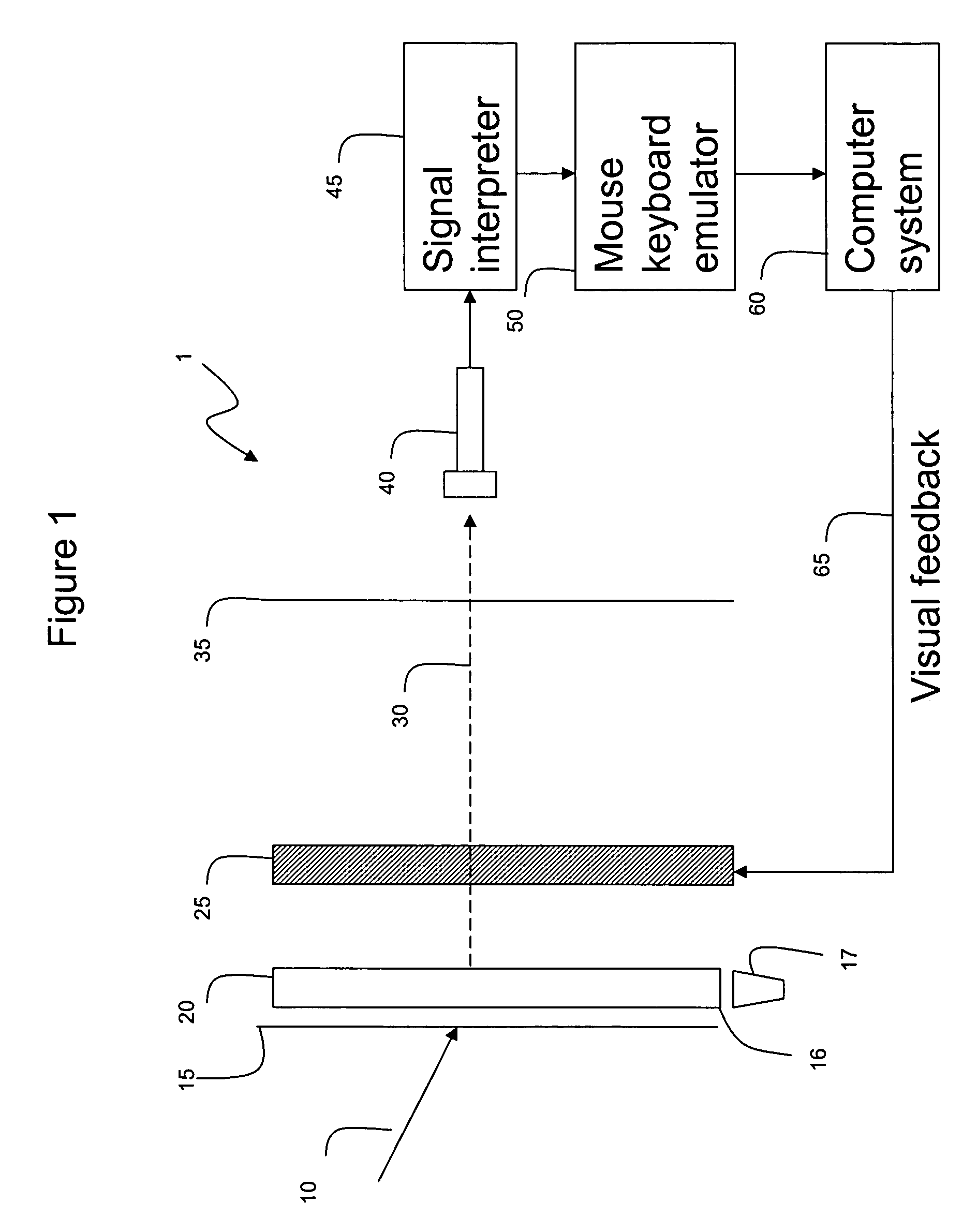
[0018]Referring now to the drawings wherein like reference characters relate to like parts there is shown one basic exemplary embodiment of a touchscreen panel system 1 for providing position input to a computer display. Element 25 is an LCD or other computer display screen, such as an OLED display. The screen receives its images from a computer system 60. Element 20 is a transparent panel, which is flooded with light on its edge 16 by a lighting element 17. A physical input stimulus 10, which can be a finger or other pointing implement, is shown touching a silicone sheet 15 located over the element 20. The sheet 15 is in optical interface contact with the panel 20. Due to the effect of Frustrated Total Internal Reflection (FTIR), a light ray 30 is refracted out of the panel 20 where the stimulus 10 touches the panel. The silicone sheet 15 indents to interface more closely to the touch panel 20 creating a more uniform response to the stimulus 10, so that different sized pointers and...


PUM


Abstract

A method and an apparatus are disclosed for determining the position of a stimulus in two axes on a surface. The apparatus includes: a transparent waveguide panel with parallel top and a bottom surfaces and at least one edge that is perpendicular to the top and bottom surfaces; a light source that is directed to the edge of the waveguide to produce light that is contained within the waveguide by Total Internal Reflection and a light detector for producing an electrical signal that is representative of an image of the light emitted by the waveguide. The light detector is positioned to receive light emitted by Frustrated Total Internal Reflection from the transparent wave guide when a physical stimulus is placed in contact with the top surface of the transparent waveguide.

Description

CROSS-REFERENCE TO RELATED APPLICATIONS[0001]This application claims priority to, and the benefit of U.S. Provisional Application No. 60 / 665,727, filed Mar. 28, 2005 for all subject matter common to both applications. The disclosure of said provisional application is hereby incorporated by reference in its entirety.FIELD OF INVENTION[0002]This invention relates generally to input devices for display screens and more particularly to a system and method for detecting the position of a finger or similar object on a flat transparent surface for use as an interactive two dimensional position input device in conjunction with pointer(s) displayed on a computer or other display screen.BACKGROUND[0003]Pointer input devices, such as mice, touch pads and the like have been integral parts of computer systems since the advent of graphical user interfaces. In many instances, such as self serve ticket vending terminals and automated teller machines, these devices are impractical and direct tactile...

Claims


Application Information

Patent Timeline
Patent Type & Authority Patents(United States)
IPC IPC(8): G06F3/042
CPCG06F3/0425G06F2203/04109
Inventor EIKMAN, ADAM
Owner EIKMAN ADAM
Why Eureka
Try Eureka