
Carrier phase ambiguity correction

a carrier phase and ambiguity correction technology, applied in the field of communication systems, can solve problems such as failure, and achieve the effect of improving performance and improving the subsequent calculation of the channel virtual center

Inactive Publication Date: 2010-04-27
THOMSON LICENSING SA
View PDF10 Cites 0 Cited by
  • Summary
  • Abstract
  • Description
  • Claims
  • Application Information

AI Technical Summary

Benefits of technology

The patent text describes a new approach for removing carrier phase ambiguity in a demodulator by identifying a correct carrier phase for use in removing carrier phase ambiguity in the demodulator. This approach addresses the impact of wrong carrier phase on the data provided as an input to the centroid calculator and the centroid estimate. The invention also includes an adaptive equalizer for correcting carrier phase ambiguity prior to the centroid calculation. The technical effect of the invention is to improve the accuracy and performance of the demodulator and the adaptive equalizer in removing carrier phase ambiguity.

Problems solved by technology

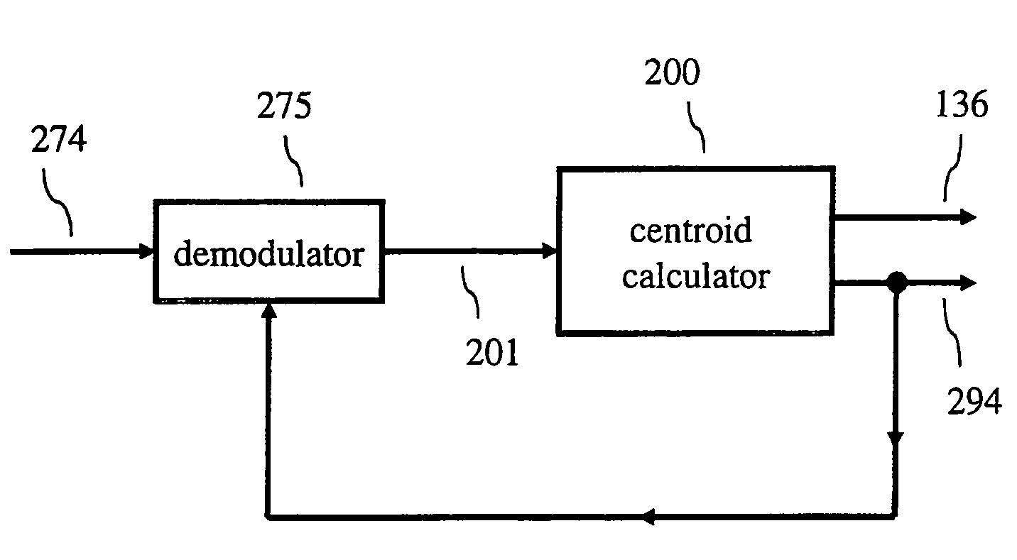
We have observed that the above-mentioned approaches for determining the channel virtual center do not address the impact of wrong carrier phase on the data that is provided as an input to the centroid calculator and consequently, on the centroid estimate.
In other words, the above-mentioned approaches do not address the effect of demodulator carrier phase ambiguity in the centroid calculation and do not attempt to correct for this ambiguity.

Method used


Image

  • Carrier phase ambiguity correction
  • Carrier phase ambiguity correction
  • Carrier phase ambiguity correction

Examples


Embodiment Construction

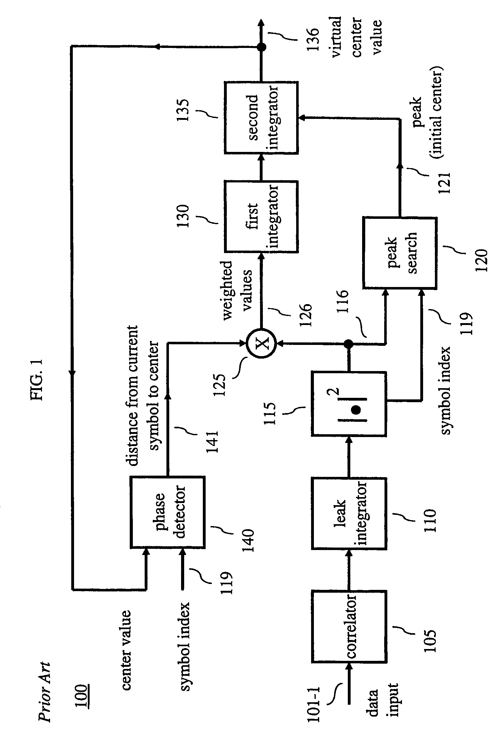
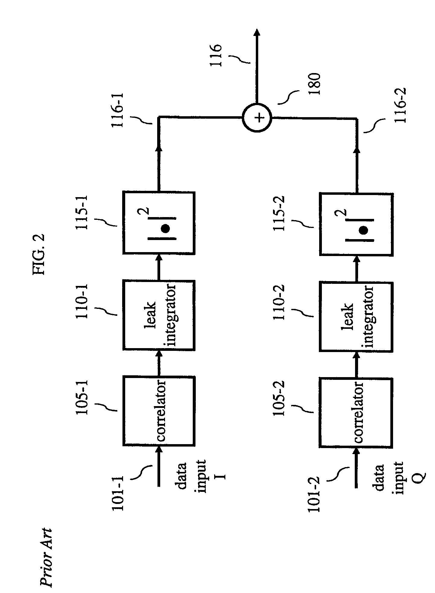
[0019]Other than the inventive concept, the elements shown in the figures are well known and will not be described in detail. Also, familiarity with television broadcasting and receivers is assumed and is not described in detail herein. For example, other than the inventive concept, familiarity with current and proposed recommendations for TV standards such as NTSC (National Television Systems Committee), PAL (Phase Alternation Lines), SECAM (SEquential Couleur Avec Memoire) and ATSC (Advanced Television Systems Committee) (ATSC) is assumed. Likewise, other than the inventive concept, transmission concepts such as eight-level vestigial sideband (8-VSB), Quadrature Amplitude Modulation (QAM), and receiver components such as a radio-frequency (RF) front-end, or receiver section, such as a low noise block, tuners, demodulators, correlators, leak integrators and squarers is assumed. Similarly, formatting and encoding methods (such as Moving Picture Expert Group (MPEG)-2 Systems Standard...


PUM


Abstract

A receiver comprises a demodulator for providing a demodulated signal and a centroid calculator responsive to the demodulated signal for identifying a correct carrier phase for use in the centroid calculation and in removing carrier phase ambiguity in the demodulator. In addition, the centroid calculator may include a limiter.

Description

[0001]This application is a National Stage Application and claims the benefit, under 35 U.S.C. §365 of International Application PCT / US2005 / 10519 filed Mar. 29, 2005, which was published in accordance with PCT Article 21(2) on Dec. 1, 2005 in English, and which claims the benefit of U.S. provisional patent application Nos. 60 / 570,298 and 60 / 570,295, which were both filed on May 12, 2004. This application is related to, commonly assigned, U.S. patent applications Ser. No. 11 / 579,845 SYMBOL TIMING AMBIGUITY CORRECTION, filed on Nov. 8, 2006; and Ser. No. 11 / 596,339 entitled COMPLEX CORRELATOR FOR A VESTIGIAL SIDEBAND MODULATED SYSTEM, filed on Nov. 9, 2006.BACKGROUND OF THE INVENTION[0002]The present invention generally relates to communications systems and, more particularly, to a receiver.[0003]In modern digital communication systems like the ATSC-DTV (Advanced Television Systems Committee-Digital Television) system (e.g., see, United States Advanced Television Systems Committee, “A...

Claims


Application Information

Patent Timeline
Patent Type & Authority Patents(United States)
IPC IPC(8): H03D1/00
CPCH04L27/0014H04L2027/0046H04L2027/0093H04L2027/0067H04L2027/0053
Inventor MARKMAN, IVONETEEDDE, GABRIEL ALFRED
Owner THOMSON LICENSING SA
Learn More