
Direct hydrocarbon fuel cells

a fuel cell and hydrocarbon technology, applied in the field of direct hydrocarbon fuel cells, can solve the problems of prohibitively large pt loading of anodes, low power density of direct-methanol polymer electrolyte fuel cells, and difficulty in achieving high-efficiency fuel cells, and achieve high power-to-volume ratios, reduce the number of seals, and reduce the electrical losses of pressure contacts

Inactive Publication Date: 2010-05-04
NORTHWESTERN UNIV
View PDF20 Cites 15 Cited by
  • Summary
  • Abstract
  • Description
  • Claims
  • Application Information

AI Technical Summary

Benefits of technology

[0014]It can be an object of the present invention to increase the rate of hydrocarbon oxidation so as to increase and / or otherwise provide useful power densities. Such densities can be increased and / or provided utilizing various catalytic metals in the fabrication of fuel cell anodes, such anodes as can be used in conjunction with a ceria material.
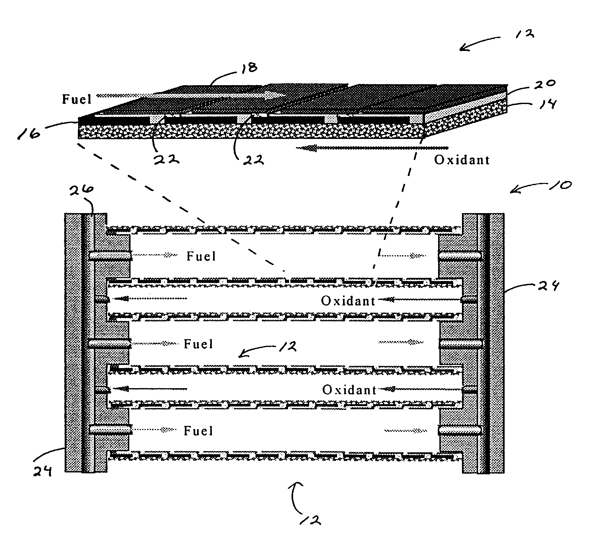
[0050]5. Large integrated stack elements can be made by increasing the number of cells: there is no need to make very large area cells.

Problems solved by technology

However, fuel cells typically operate only with hydrogen as the fuel.
Prior art fuel cells utilizing hydrocarbon fuels directly have encountered significant problems.
For example, direct-methanol polymer electrolyte fuel cells produce relatively low power densities and require prohibitively large Pt loading of the anodes.
Furthermore, only alcohol fuels appear feasible with this approach.
However, maintaining appropriate gas composition and temperature gradients across a large area SOFC stack is challenging.
For instance, if the reforming reactions are slow, then insufficient H2 is supplied to the SOFCs.
On the other hand, fast reforming reactions cause cooling localized near the fuel inlet, leading to poor cell performance, and possible cell fracture.
Thus, current SOFC stacks of the prior art do not take full advantage of internal reforming; rather, they employ a combination of ≈75% external and 25% internal reforming of hydrocarbon fuels.
However, prior art attempts with SOFCs operating at temperatures Tc=900-1000° C. with methane fuel have been less than satisfactory: either power densities were very low or carbon deposition was observed.
However, such systems have not been considered or used for direct-hydrocarbon operation, because carbon deposition reaction rates decrease with decreasing temperature.
Tubular stacks avoid sealing and manifolding problems inherent to planar stacks, but take a large volume for a given cell active area and can show significant ohmic losses related to current transport around the tube circumference through the (La,Sr)MnO3 (LSM) cathode.
Another problem is the relatively poor mechanical toughness of LSM.
Alternatively, planar stacks can provide higher power-to-volume ratios than tubular stacks, but are not as mechanically robust as tubes and require excellent seals.
Another problem with many planar stack designs is that they require pressure contacts between separate SOFC and interconnect plates.
This places stringent requirements on the flatness of large-area ceramic plates, making manufacturing difficult and expensive.
Furthermore, there are often relatively high resistances associated with these contacts, which deleteriously affect stack performance.
Even so, the disadvantages associated with each respective approach present obstacles for effective use of SOFCs and suggest a new direction is needed to better utilize and benefit from this technology.

Method used


Image

  • Direct hydrocarbon fuel cells
  • Direct hydrocarbon fuel cells
  • Direct hydrocarbon fuel cells

Examples


example 1

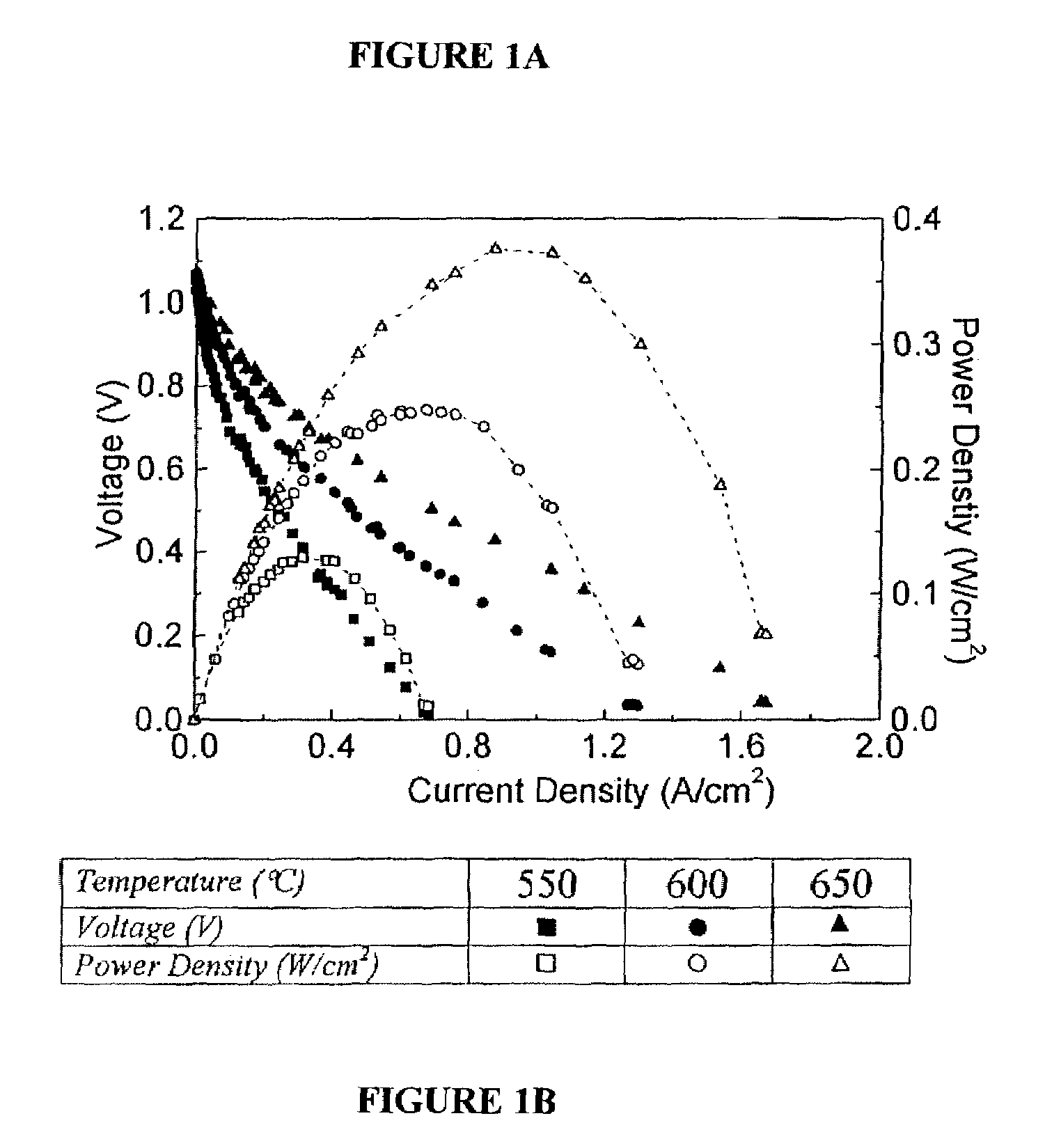
[0100]Single-cell current-voltage measurements were carried out in air and methane. Identical results were obtained for pure and humidified (containing 3% H2O) methane in the early stages of cell tests; while cell performance was stable with dry methane, after ≈2 hrs of testing in humidified methane, cell performance degraded because of oxidation of the anode Ni. FIG. 1 shows the measured current density and power density vs. voltage. The open-circuit voltage (OCV) was 1.06V. The current density vs. voltage curves were non-ohmic indicating a substantial electrode overpotential. Based on prior studies of these cells operated on hydrogen fuel, the current densities were limited primarily by cathode, overpotential. Current densities increased with increasing temperature, such that maximum power density increased from 250 mW / cm2 at 600° C. to 370 mW / cm2 at 650° C.

example 2

[0101]By way of comparison, the results of Example 1 were similar to those obtained for cells operated with humidified hydrogen fuel, except that the power densities were ≈20% greater. Visual observation, energy dispersive x-ray (EDX), and scanning electron microscopy (SEM) observations of the anodes, carried out after the call tests, showed no evidence of carbon deposition after ≈100 hrs of operation.

example 3

[0102]Successful cell operation on dry methane (Example 1) indicated that direct electrochemical oxidation,

CH4+2O2=2H2O+CO2 ΔG°(600° C.)=−800 kJ / mol  (3)

was the primary anode reaction mechanism. The OCV values measured in Example 1, ≈1.06V, were typically very close to the values measured for these cells operated with 97% H2+3% H2O fuel. This is reasonable given that the ΔG°(600° C.) values are similar for eqn. 3 and hydrogen oxidation. The exact Nernst potential for eqn. 3 cannot be calculated since the, H2O and CO2 partial pressures are not known, but the measured OCVs suggest reasonable values, 2O and 2.

[0103]While eqn. 3 shows electrochemical oxidation of methane, it should be noted that the present invention contemplates the possibility of other reaction mechanisms for the desired oxidation products. For instance, various intermediate reactions and / or species can exist enroute to complete oxidation under cell operating conditions. While eqn. 3 illustrates methane oxidation, equ...


PUM

PropertyMeasurementUnit
temperatureaaaaaaaaaa
operating temperatureaaaaaaaaaa

Abstract

The direct electrochemical oxidation of hydrocarbons in solid oxide fuel cells, to generate greater power densities at lower temperatures without carbon deposition. The performance obtained is comparable to that of fuel cells used for hydrogen, and is achieved by using novel anode composites at low operating temperatures. Such solid oxide fuel cells, regardless of fuel source or operation, can be configured advantageously using the structural geometries of this invention.

Description

[0001]This is a continuation-in-part application of and claims priority benefit from pending International Application PCT / US02 / 11050, with an international filing date of Apr. 9, 2002, published in English under PCT Article 21(2), designating the United States of America, and U.S. application Ser. No. 09 / 833,209, filed on Apr. 10, 2001, now issued as U.S. Pat. No. 6,479,178, each of which is incorporated herein in its entirety.[0002]The United States government has certain rights to this invention pursuant to Grant No. DE-G626-00NT40814 from the Department of Energy to Northwestern University.FIELD OF THE INVENTION[0003]This invention relates generally to fuel cells and assemblies, more particularly, cells and components thereof as can be configured for use with hydrogen fuel or the direct oxidation of hydrocarbons.BACKGROUND OF INVENTION[0004]Fuel cells are promising electrical power generation technologies, with key advantages including high efficiency and low pollution. Most pot...

Claims


Application Information

Patent Timeline
Patent Type & Authority Patents(United States)
IPC IPC(8): H01M8/10H01M2/00H01M2/02H01M2/14H01M2/08H01M2/18H01M4/86H01M4/88H01M4/90H01M4/92H01M4/96H01M8/00H01M8/02H01M8/04H01M8/06H01M8/12H01M8/18H01M8/24
CPCH01M4/8621H01M4/9066H01M8/0637H01M8/1213H01M8/1253H01M8/126H01M8/1286H01M8/2425H01M4/90Y02E60/525H01M4/9033H01M4/92H01M8/0202H01M8/0219H01M8/0612H01M8/1226H01M2008/1293Y02E60/521Y02E60/50Y02P70/50H01M8/2428H01M8/2432
Inventor BARNETT, SCOTT A.LAI, TAMMYLIU, JIANG
Owner NORTHWESTERN UNIV
Learn More