Check patentability & draft patents in minutes with Patsnap Eureka AI!

Method for imaging a lithographic printing form

a technology of lithographic printing and imaging form, which is applied in the field of imaging lithographic printing form, can solve the problem that the difference in the level of wetting between the hydrophilic and hydrophobic regions can still not be adequately high for lithographic printing, and achieve the effect of low radiation output and low power density

Inactive Publication Date: 2010-05-04
HEIDELBERGER DRUCKMASCHINEN AG
View PDF12 Cites 0 Cited by
  • Summary
  • Abstract
  • Description
  • Claims
  • Application Information

AI Technical Summary

Benefits of technology

This method allows for the efficient creation of structured hydrophilic and hydrophobic regions with reduced radiation power, enabling faster imaging and repeated use of lithographic printing forms, utilizing lower power densities and commercially available equipment.

Problems solved by technology

After the treatment and before the treatment with the complex-forming substance, there can still be no structure with hydrophilic and hydrophobic regions on the printing area, or the difference in the level of wetting between the hydrophilic and hydrophobic regions can still not be adequately high for the lithographic printing.

Method used


Image

  • Method for imaging a lithographic printing form
  • Method for imaging a lithographic printing form
  • Method for imaging a lithographic printing form

Examples


Embodiment Construction

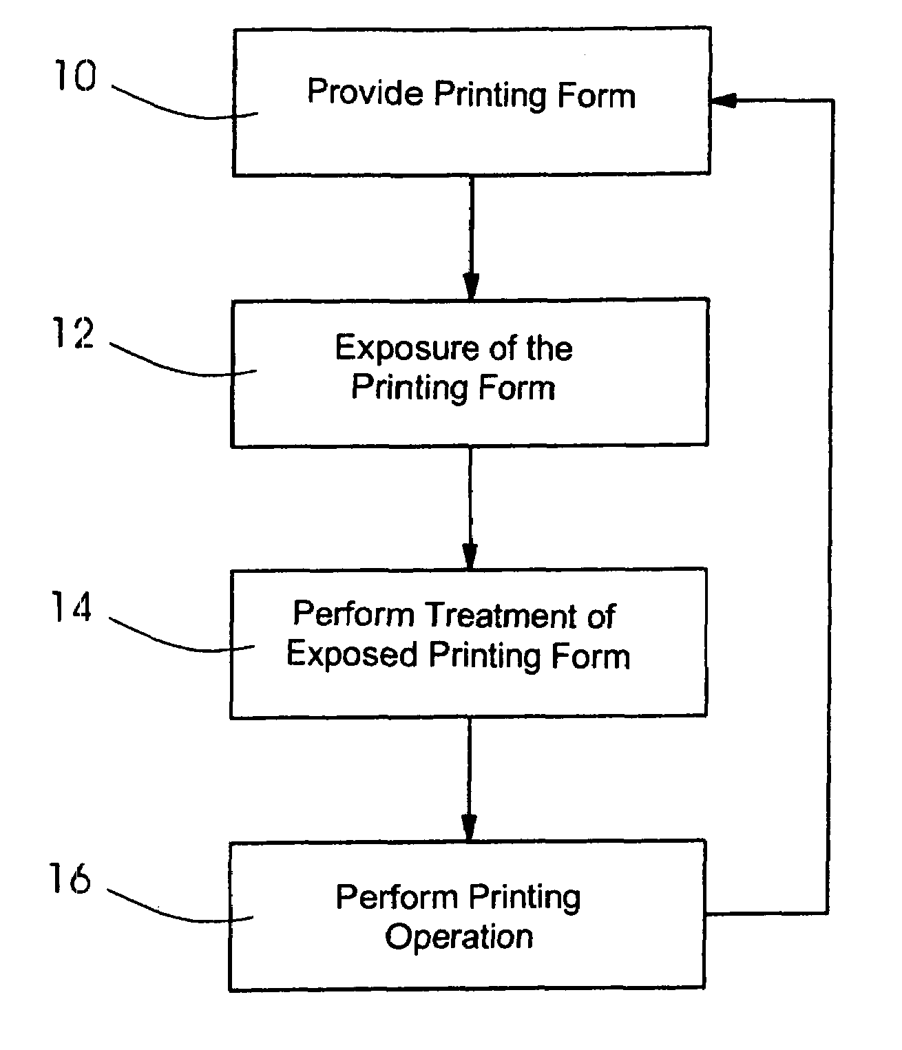
[0038]Referring now to the figures of the drawing in detail and first, particularly, to FIG. 1 thereof, there is shown a flow chart of a preferred embodiment of the method according to the invention. For a lithographic printing process, in particular an offset printing process, a surface having a layer, in particular a microscopic layer, for example a monolayer, of amphiphilic molecules is provided in step 10. The part of the surface which subsequently represents a printing area is initially unstructured, that is to say substantially homogeneous and densely covered by amphiphilic molecules. As a result of the covering, because of the hydrophobic side of the amphiphilic molecules facing away from the surface, the printing area is substantially homogeneously hydrophobic (in this regard, see also FIG. 2). This initial state can be reproduced repeatedly, so that the method described below can be applied repeatedly for various structure patterns (printing subjects). More details relating...


PUM

PropertyMeasurementUnit
diameteraaaaaaaaaa
imaging speedaaaaaaaaaa
hydrophilicaaaaaaaaaa

Abstract

In a method for imaging a lithographic printing form, subareas of a surface of the lithographic printing form which are covered by amphiphilic molecules, are exposed to electromagnetic radiation. Following the exposure and before printing from the lithographic printing form, the subareas are treated with at least one complex-forming substance, so that a lithographic printing area structured into hydrophilic and hydrophobic regions is obtained.

Description

CROSS-REFERENCE TO RELATED APPLICATION[0001]This application claims the priority, under 35 U.S.C. §119, of German application DE 10 2006 013 753.1, filed Mar. 24, 2006; the prior application is herewith incorporated by reference in its entirety.BACKGROUND OF THE INVENTIONField of the Invention[0002]The invention relates to a method for imaging a lithographic printing form, in which subareas of a surface of the lithographic printing form which are covered by amphiphilic molecules are exposed to electromagnetic radiation.[0003]During the imaging of a lithographic printing form which has areas covered by amphiphilic molecules, a high radiation output, in particular laser output, is typically necessary in order that structuring into hydrophilic (damping solution carrying) and hydrophobic (ink accepting) regions is achieved directly by the supply of energy, so that a printing area for lithographic printing is obtained.[0004]In published, non-prosecuted German patent application DE 102 27...

Claims


Application Information

Patent Timeline
Patent Type & Authority Patents(United States)
IPC IPC(8): G03F7/00G03F7/04
CPCB41C1/10G03F7/165G03F7/40G03F7/26G03F7/36
Inventor SCHLORHOLZ, MATHIASLATZEL, HARALDVOSSELER, BERND
Owner HEIDELBERGER DRUCKMASCHINEN AG
Features
  • R&D
  • Intellectual Property
  • Life Sciences
  • Materials
  • Tech Scout
  • Unparalleled Data Quality
  • Higher Quality Content
  • 60% Fewer Hallucinations
Learn More