Method for reconstructing a three-dimensional image volume and x-ray devices

a three-dimensional image and volume technology, applied in the field of three-dimensional image volume and x-ray device reconstruction, can solve the problems of transaxial truncated projection, difficult to qualify diagnosis, and often not being able to reconstruct the complete region of interest, and achieve the effect of advantageous execution

Inactive Publication Date: 2010-05-04
SIEMENS HEALTHCARE GMBH
View PDF11 Cites 204 Cited by
  • Summary
  • Abstract
  • Description
  • Claims
  • Application Information

AI Technical Summary

Benefits of technology

[0016]The region is herewith extended in a simple and uncomplicated manner, said region being mapped from all curve points of the scanning path curve in two-dimensional projection images, thereby also enabling it to be reconstructed without artifacts and in a three-dimensional manner. The scanning path curve or trajectory is herewith defined by the path of the x-ray focus.
[0034]The method according to the invention is particularly advantageously executed with an x-ray device, with which the recording system is arranged on an industrial robot and / or articulated arm robot directly or by means of a bracket or with which the couch is arranged on an industrial robot and / or articulated arm robot. Such an x-ray device enables any movements in the space to be carried out in a simple fashion.

Problems solved by technology

In many recordings, the limited detector width however results in transaxially truncated projections of the region of interest, since this cannot be completely covered by the field of view (FoV).
The results are significant reconstruction artifacts, such as for instance so-called truncation artifacts, which distort the result and hinder, complicate or render impossible the qualified diagnosis thereof.
More recent precise reconstruction methods (such as for instance known from A. Katsevich: “Image Reconstruction for the Circle and Arc Trajectory”, Physics in Medicine and Biology, Vol. 50, pages 2249-2265, April 2005 and from J. Pack, F. Noo: “Cone-Beam Reconstruction Using ID Filtering Along the Projection of M-Lines”, Inverse Problems, Vol. 21, pages 1105-1120, April 2005) require extended path curves for scanning (such as circle and line, circle and circle arc), but nevertheless feature this problem.
The region of interest is however limited to the field of view (FoV), so that even with this method, it is frequently not possible to reconstruct the complete region of interest (such as for instance abdomen of a large patient).
Furthermore, with cone-beam geometry, this method represents an approximate field of view (FoV) enlargement and thus results in artifacts in the event of large cone angles.

Method used


Image

  • Method for reconstructing a three-dimensional image volume and x-ray devices
  • Method for reconstructing a three-dimensional image volume and x-ray devices
  • Method for reconstructing a three-dimensional image volume and x-ray devices

Examples


Embodiment Construction

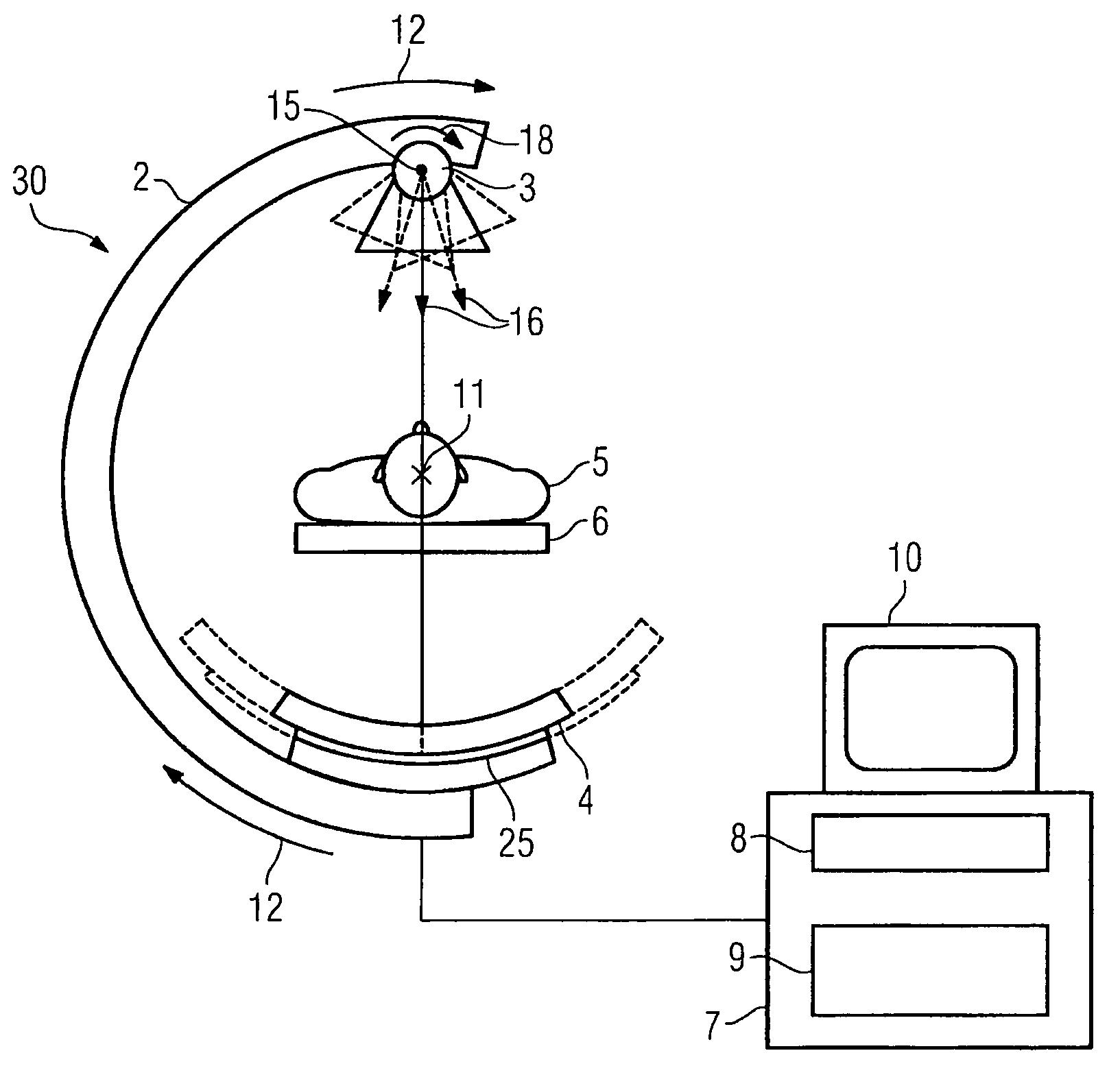
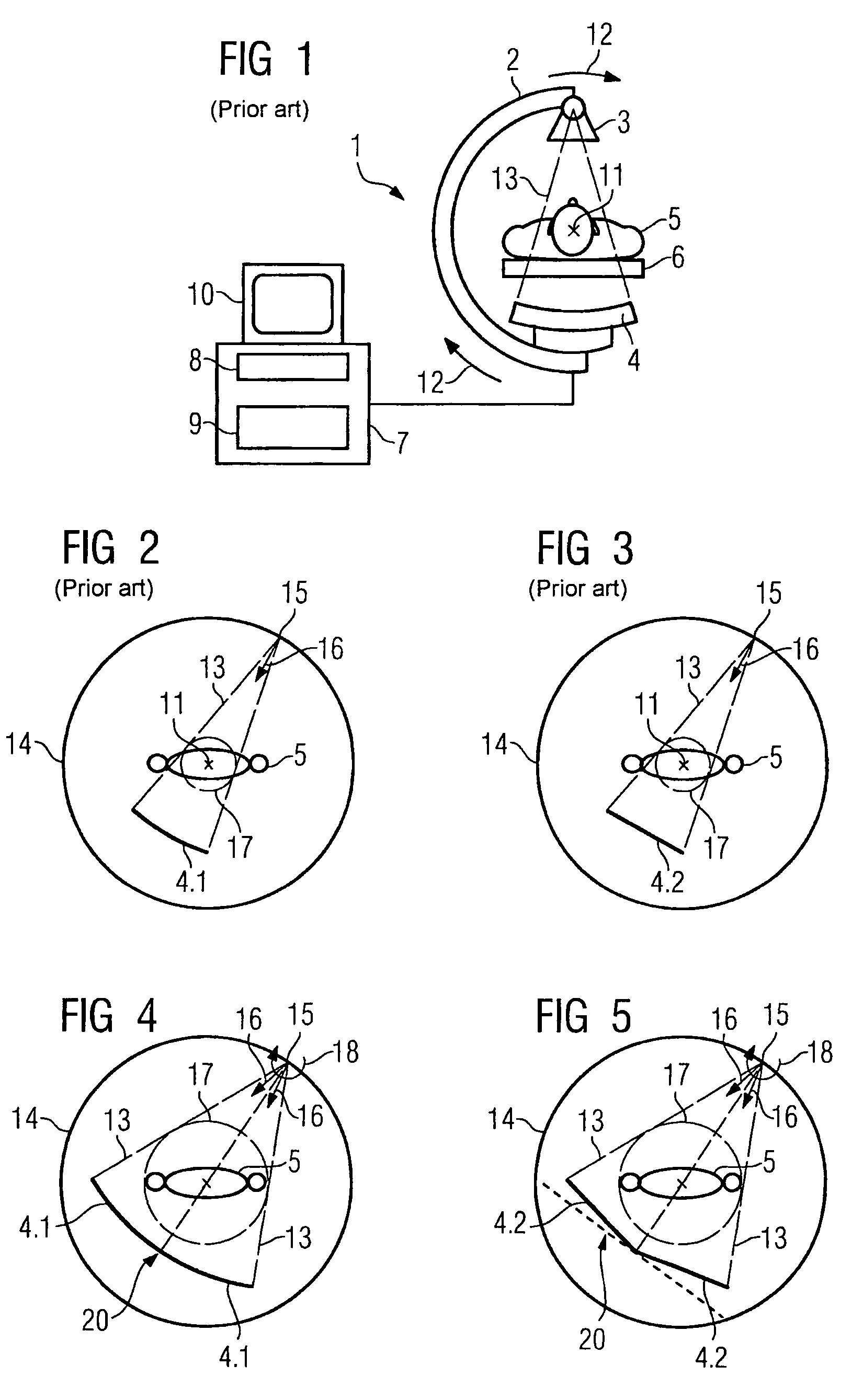
[0059]FIG. 1 shows a schematic representation of a C-arm x-ray system 1, which comprises a C-arm 2, to which an x-ray source 3 and an x-ray detector 4 disposed opposite to each other are attached, generally in fixed alignment. The x-ray detector 4 can be a flat or curved x-ray detector 4 based on a solid body for instance. Such an x-ray detector 4 can comprise a scintillator for instance and a detector matrix with pixel elements. The x-ray source 3 generates an x-ray beam 13. The C-arm can be rotated (angled) about a region of interest 5 which is located on a patient bed 6, for instance by rotation about a first rotation axis 11 in the direction of the arrow 12 for instance. In this process, 2D projection images are recorded for different angular positions from the respective projection directions of the recording system. The region of interest 5 is arranged here such that its center point lies on the axis of rotation 11.

[0060]The 2D projection images thus obtained are forwarded to ...


PUM


Abstract

To enable an artifact free reconstruction even in the case of large regions of interest and with scanning paths of below 360°, provision is made for a method, with which a three-dimensional image volume is reconstructed from a number of two-dimensional projection images of a region of interest, which were recorded about the region of interest during a rotation of a recording system, comprising an x-ray source with a focal point and a detector, by calculating the gray scale values of the voxels of the image volume by back projection of the projection images, with which each two-dimensional projection images is composed in each instance from at least two individual projection images to form an extended two-dimensional projection image, with the respectively at least two individual projection images being recorded with a constant relative position between the focal point and the region of interest.

Description

CROSS REFERENCE TO RELATED APPLICATIONS[0001]This application claims priority of German application No. 10 2006 041 033.5 filed Sep. 1, 2006, which is incorporated by reference herein in its entirety.FIELD OF THE INVENTION[0002]The invention relates to a method for reconstructing a three-dimensional image volume from two-dimensional projection images of an object as well as an x-ray device for implementing a method of this type and a further x-ray device for implementing a method of this type as claimed in the claims.BACKGROUND OF THE INVENTION[0003]With the current three-dimensional cone beam reconstruction with the aid of C-arm systems, the so-called Wide Object Problem arises during the examination of certain body regions (such as for instance abdomen or breast), which exceed a maximum width determined by the recording geometry (detector dimension and focal length). A decisive processing step for 3D reconstruction using filtered back projection is the filtering of the projection ...

Claims


Application Information

Patent Timeline
Patent Type & Authority Patents(United States)
IPC IPC(8): A61B6/00A61B6/03
CPCA61B6/032G01N23/046A61B6/4458G01N2223/612G01N2223/419A61B6/027
Inventor HEIGL, BENNOHOPPE, STEFANHORNEGGER, JOACHIMRUHRNSCHOPF, ERNST-PETERSCHERL, HOLGERSCHOLZ, BERNHARDZELLERHOFF, MICHAEL
Owner SIEMENS HEALTHCARE GMBH
Why Eureka
Try Eureka