
Controlling direction of ultrasound imaging catheter

Inactive Publication Date: 2007-05-10
BIOSENSE WEBSTER INC
View PDF18 Cites 80 Cited by
  • Summary
  • Abstract
  • Description
  • Claims
  • Application Information

AI Technical Summary

Benefits of technology

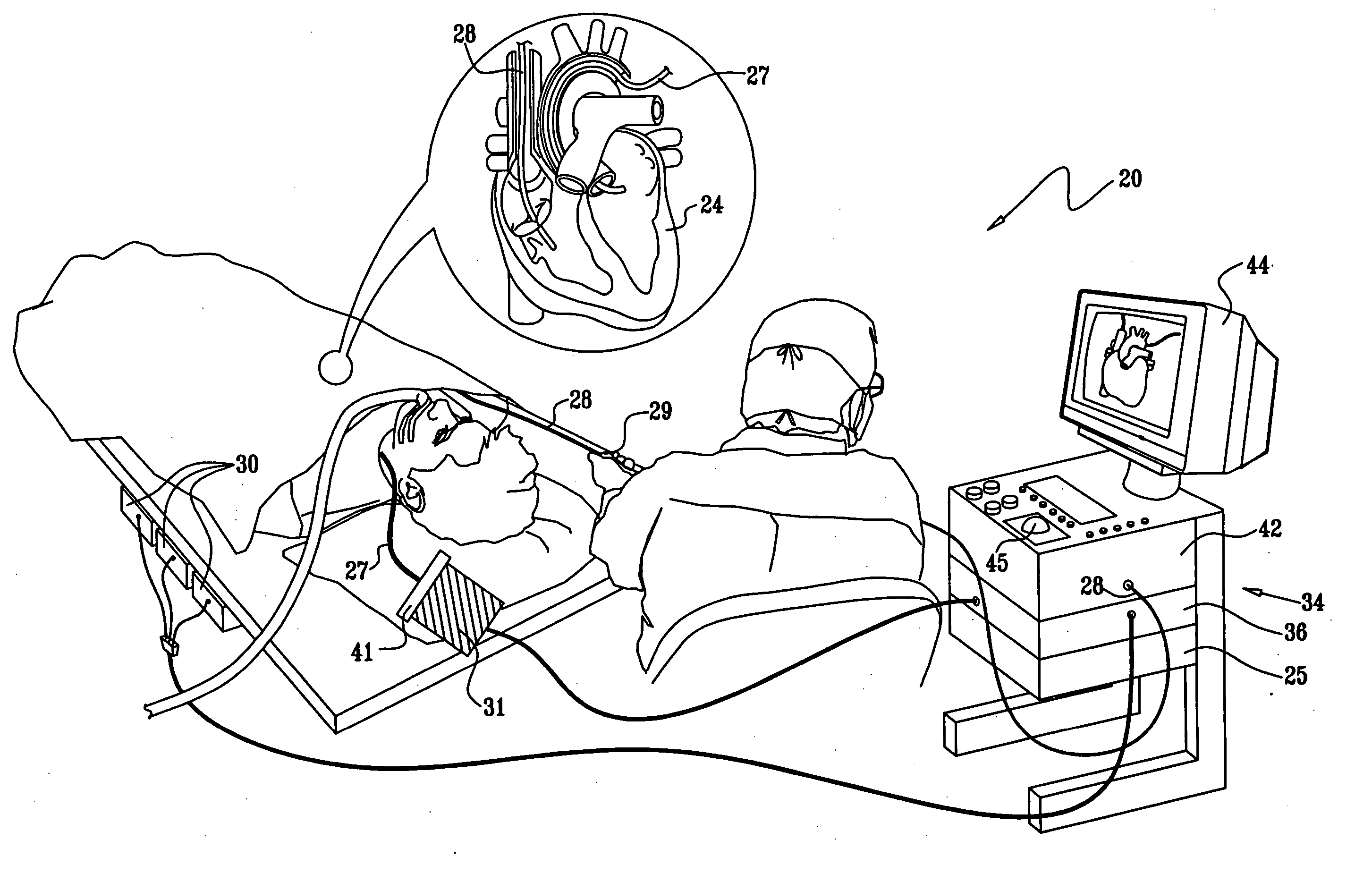
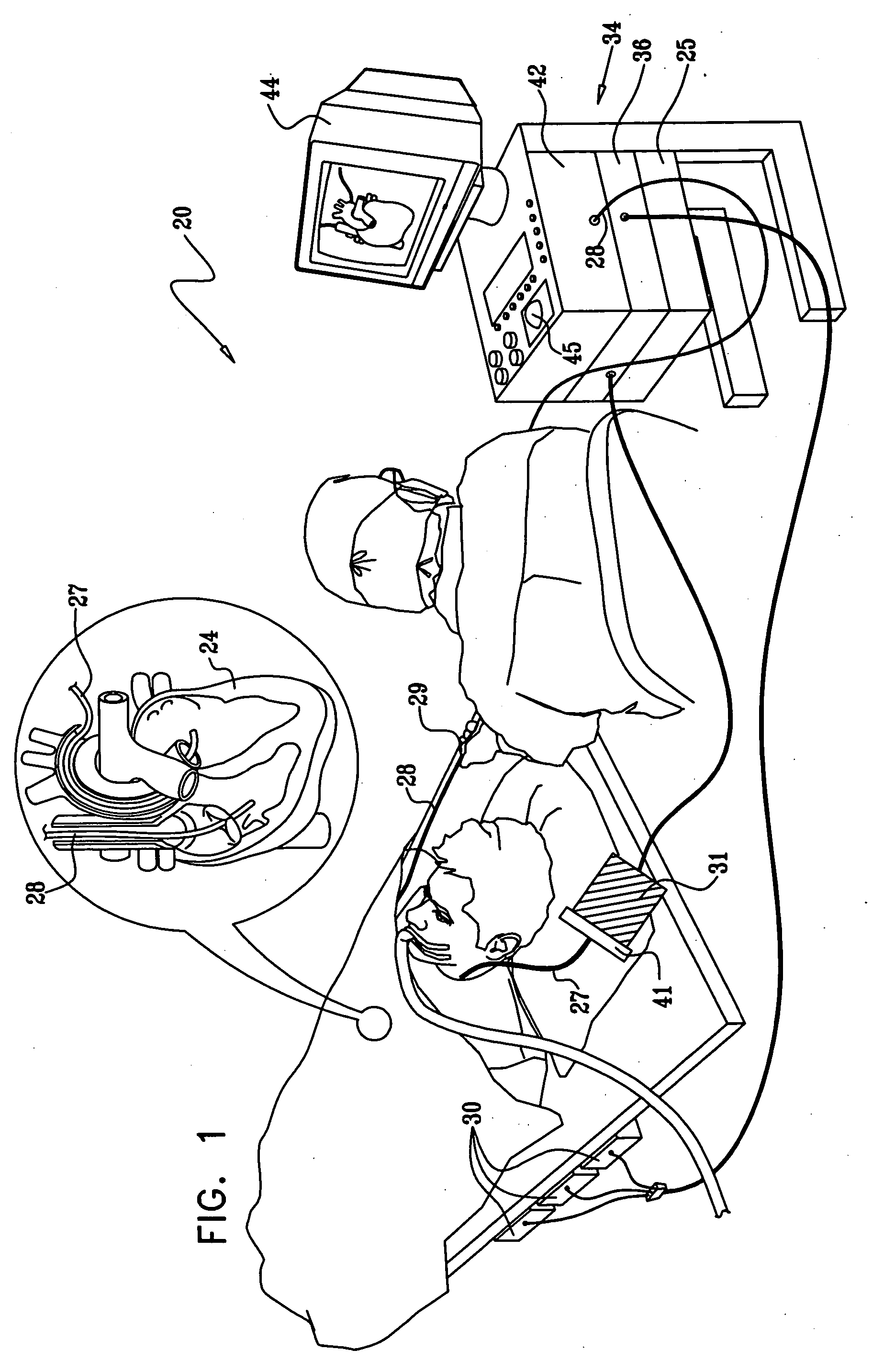
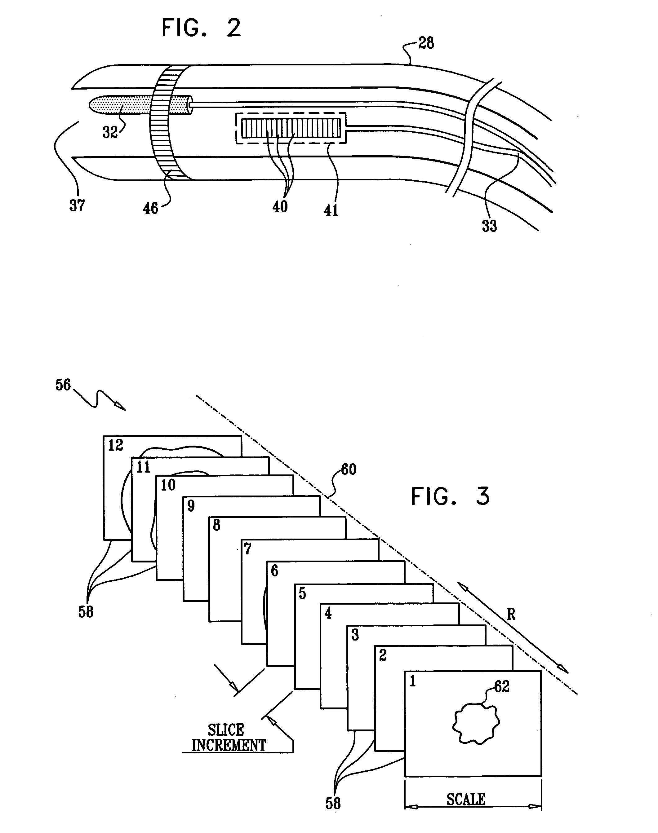
[0008] Hybrid catheters, for example, catheters having ultrasound transducers and a location sensor provide real-time visualization of anatomical structures and of surgical procedures. The catheter field of view and the resulting ultrasound images have the form of a two-dimensional “fan,” which opens outward from the catheter tip and provides a sectional image of the tissue that it intersects. If the location or orientation of the tip is incorrect or unstable, the fan may fail to capture a desired structure or may lose the structure during viewing. Disclosed embodiments of the present invention provide methods and systems for directing and stabilizing the orientation of the ultrasound beam. This is particularly useful in imaging an area in which a surgical procedure is being performed. For example, ultrasound imaging can verify that an ablation catheter is in place and in contact with tissue to be ablated. Subsequent to ablation, ultrasound imaging can confirm that ablation was successful because of the change in echogenicity of the tissue. Stabilization of the catheter using the principles of the present invention ensures that the operator has accurate, near realtime visual feedback related to the target of interest. A catheter having the capabilities just described is sometimes referred to herein as an ultrasound catheter or an ultrasound imaging catheter.
[0009] In some aspects of the present invention, convenience of echocardiographic guidance in single operator intracardiac therapeutic procedures is enhanced. By robotically steering an ultrasound catheter to automatically follow the tip of an operative catheter, such as a mapping or ablating catheter, the operator is relieved of the burden of adjusting the imaging catheter to track the mapping or ablation catheter and its target. Realtime visualization of a target site is also enabled during the catheterization procedure, enabling accurate lesion targeting and optimal execution of a therapeutic ablation plan. Other advantages of the invention include monitoring catheter-tissue contact, monitoring the progress of ablation, including detection of bubble and char formation in tissues at the target.
[0013] Advantages of the present invention include improved accuracy in utilizing ultrasound imaging to track the progress of medical procedures. It relieves the operator of the continuous distraction of aiming the beam of the imaging catheter while performing a procedure. It can also be used to keep a particular structure or location within the body in the field of view of the catheter.

Problems solved by technology

If the location or orientation of the tip is incorrect or unstable, the fan may fail to capture a desired structure or may lose the structure during viewing.
Although the magnetic-based position and orientation sensor in the ultrasound catheter enables the operator to know the catheter position and orientation at all times, it does not by itself guarantee success in holding the catheter stationary in a desired position.

Method used


Image

  • Controlling direction of ultrasound imaging catheter
  • Controlling direction of ultrasound imaging catheter
  • Controlling direction of ultrasound imaging catheter

Examples


Embodiment Construction

[0038] In the following description, numerous specific details are set forth in order to provide a thorough understanding of the present invention. It will be apparent to one skilled in the art, however, that the present invention may be practiced without these specific details. In other instances, well-known circuits, control logic, and the details of computer program instructions for conventional algorithms and processes have not been shown in detail in order not to obscure the present invention unnecessarily.

[0039] Software programming code, which embodies aspects of the present invention, is typically maintained in permanent storage, such as a computer readable medium. In a client-server environment, such software programming code may be stored on a client or a server. The software programming code may be embodied on any of a variety of known media for use with a data processing system. This includes, but is not limited to, magnetic and optical storage devices such as disk driv...


PUM


Abstract

The position of an imaging catheter in a body structure such as the heart is automatically controlled by a robotic manipulator such that its field of view at all times includes the distal end of a second catheter that is employed to effect a medical procedure. A processor receives signals from position sensors in the catheters. The processor utilizes the information received from the sensors and continually determines any deviation of the second catheter from the required field of view of the imaging catheter. The processor transmits compensation instructions to the robotic manipulator, which when executed assure that the imaging catheter tracks the second catheter.

Description

BACKGROUND OF THE INVENTION [0001] 1. Field of the Invention [0002] This invention relates to sensing the position and orientation of an object placed within a living body. More particularly, this invention relates to stabilizing the position and orientation of an intravascular probe within a moving internal organ of a living body. [0003] 2. Description of the Related Art [0004] A wide range of medical procedures involve placing objects, such as sensors, tubes, catheters, dispensing devices, and implants, within the body. Realtime imaging methods are often used to assist operators in visualizing the object and its surrounding during these procedures. In most situations, however, realtime three-dimensional imaging is not possible or desirable. Instead, systems for obtaining realtime spatial coordinates of the internal object are often utilized. [0005] Many such position sensing systems have been developed or envisioned in the prior art. Some systems involve attaching sensors to the i...

Claims


Application Information

Patent Timeline
IPC IPC(8): A61B5/05A61B8/00A61B5/374A61B5/296
CPCA61B8/12A61B8/543A61B19/22A61B19/2203A61B19/5244A61B2019/528A61B2019/2226A61B2019/505A61B2019/5251A61B2019/5276A61B2019/2211A61B34/20A61B34/70A61B2034/301A61B2090/3784A61B34/30A61B2034/304A61B2034/105A61B2034/2051A61B2090/378A61M25/00
Inventor ALTMANN, ANDRES CLAUDIOEPHRATH, YARONGOVARI, ASSAF
Owner BIOSENSE WEBSTER INC
Learn More