Method and system for performing optical proximity correction with process variations considerations

a technology of optical proximity and process variation, applied in the field of photolithographic printing, can solve the problems of distortion, incompatibility of objects formed on the wafer, and the number of circuit elements to be produced on the wafer becoming increasingly large and correspondingly smaller

Inactive Publication Date: 2010-05-04
BOARD OF RGT THE UNIV OF TEXAS SYST
View PDF6 Cites 5 Cited by
  • Summary
  • Abstract
  • Description
  • Claims
  • Application Information

AI Technical Summary

Problems solved by technology

As integrated circuit designs become more complex, the number of circuit elements to be produced on a wafer become increasingly large and each object becomes correspondingly smaller.
As the size of the objects to be produced become similar in size or smaller than the wavelength of light used to illuminate the wafer, distortions occur whereby the pattern of objects formed on the wafer do not correspond to the pattern of objects defined by the mask.
However, disregarding process variations may lead to erroneous timing, power and yield characterization analysis.

Method used


Image

  • Method and system for performing optical proximity correction with process variations considerations
  • Method and system for performing optical proximity correction with process variations considerations
  • Method and system for performing optical proximity correction with process variations considerations

Examples


Embodiment Construction

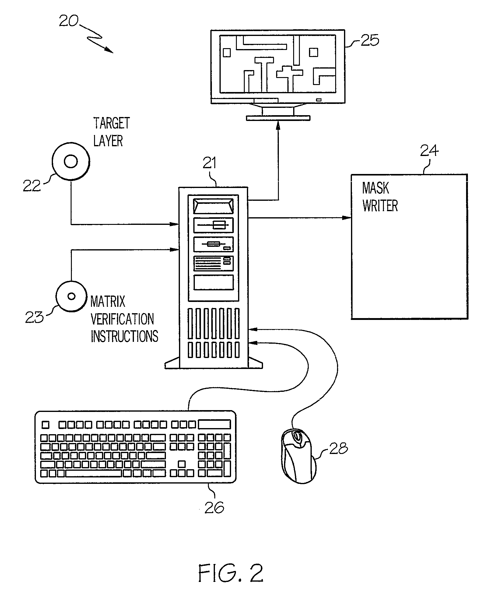
[0022]With reference now to FIG. 2, there is depicted a block diagram of a computer system in which a preferred embodiment of the present invention is incorporated. As shown, a computer system 20 includes a processing unit 21 connected to a display 25, a keyboard 26 and a mouse 28. Instructions used by processing unit 21 to implement the optical proximity correction technique of the present invention are received on a computer readable media 23 or can be received as a communication signal from a remote computer over a wired or wireless data link. Processing unit 21 receives a target layer description that defines a number of circuit elements to be manufactured on a semiconductor wafer. The target layer description is received on a computer readable media 22 or can be received from a remote computer over a wired or wireless data communication link. Processing unit 21 generates a mask layout description of one or more lithographic masks that will be used to expose desired portions of ...


PUM


Abstract

A method for performing optical proximity correction with process variations considerations is disclosed. The maximum aerial gradient direction for a control point associated with an edge is initially determined. Then, a variational edge placement error E along the maximum aerial image intensity gradient direction of the control point is calculated. A determination is made whether or not |CE·n| is equal to or greater than a manufacturing grid, where n is the direction perpendicular to a segment pointing outward, and C is a constant. If |CE·n| is equal to or greater than a manufacturing grid, the edge is moved by −CE·n.

Description

RELATED APPLICATION[0001]The present application claims priority under 35 U.S.C. §119(e)(1) to provisional application No. 60 / 951,377 filed on Jul. 23, 2007, the contents of which are incorporated herein by reference.BACKGROUND OF THE INVENTION[0002]1. Technical Field[0003]The present invention relates to photolithographic printing in general, and, in particular, to a method and system for performing optical proximity correction with process variations considerations.[0004]2. Description of Related Art[0005]When transferring an integrated circuit design pattern onto a semiconductor substrate, the most common technique is to produce a photomask with a photomask layout of the integrated circuit design, and then a lithography process is utilized to expose the patterns of the photomask layout to a semiconductor substrate in a predetermined ratio.[0006]As integrated circuit designs become more complex, the number of circuit elements to be produced on a wafer become increasingly large and...

Claims


Application Information

Patent Timeline
Patent Type & Authority Patents(United States)
IPC IPC(8): G06F17/50G06F17/00
CPCG03F1/36G03F1/144
Inventor PAN, ZHIGANGYU, PENG
Owner BOARD OF RGT THE UNIV OF TEXAS SYST
Why Eureka
Try Eureka