Energy transfer system and associated methods

a technology of energy transfer and associated methods, applied in the field of energy transfer, can solve the problems of high labor intensity and cost, high risk of being damaged by nature forces, and the installation of such pipes generally requires disturbing the shoreline,

Active Publication Date: 2010-05-11
COTHERM OF AMERICA CORP
View PDF10 Cites 17 Cited by
  • Summary
  • Abstract
  • Description
  • Claims
  • Application Information

AI Technical Summary

Problems solved by technology

This type of installation, however, is highly labor-intensive and costly.
Pipes, such as those referenced above are also normally exposed within the water source and, accordingly, are at risk for being damaged by forces of nature, e.g., earthquakes, hurricanes, or violent currents.
Installation of such pipes also generally requires disturbing the shore line.
The exposure of these pipes to the water source disadvantageously decreases the life cycle of the pipes.

Method used


Image

  • Energy transfer system and associated methods
  • Energy transfer system and associated methods
  • Energy transfer system and associated methods

Examples


Embodiment Construction

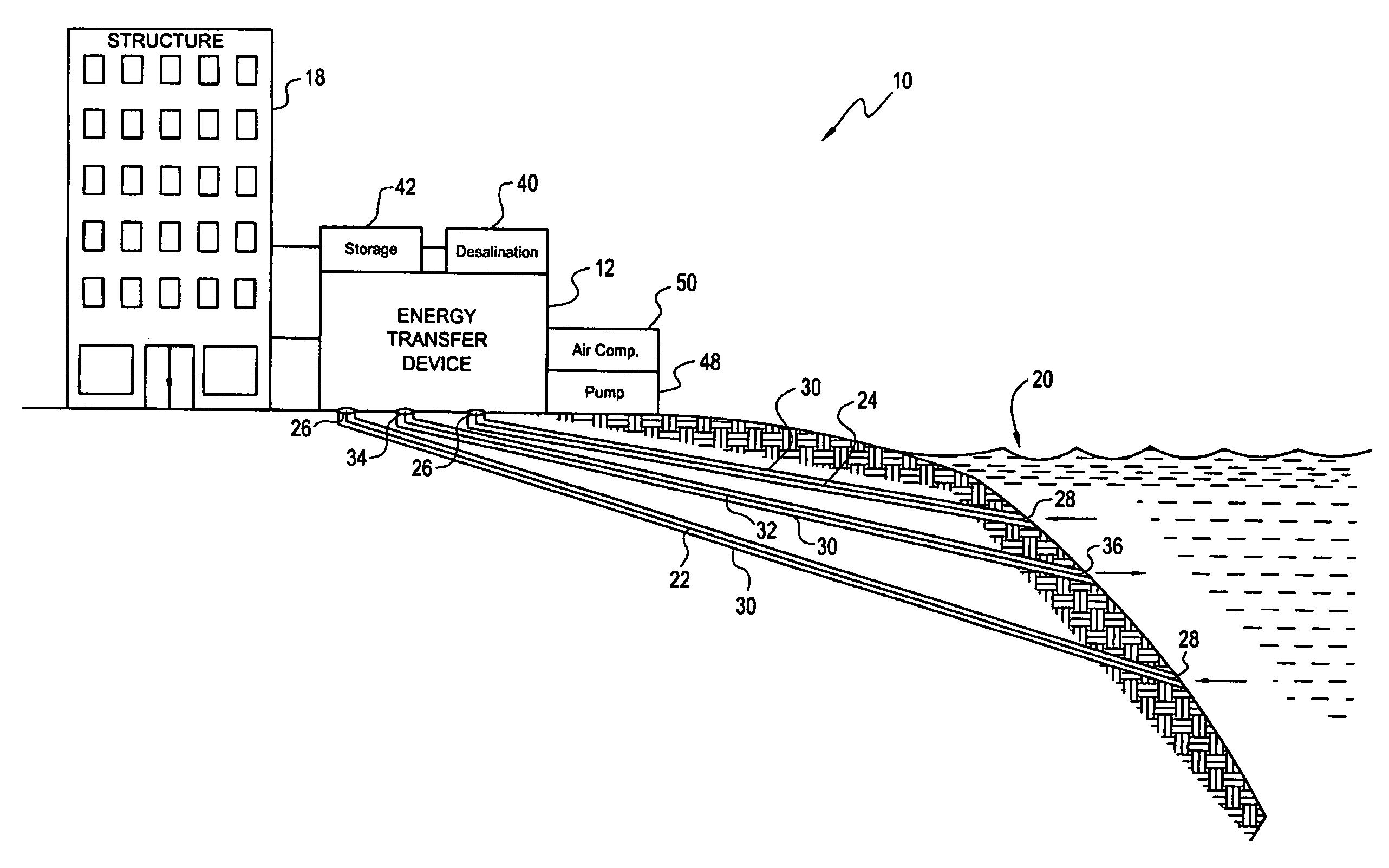
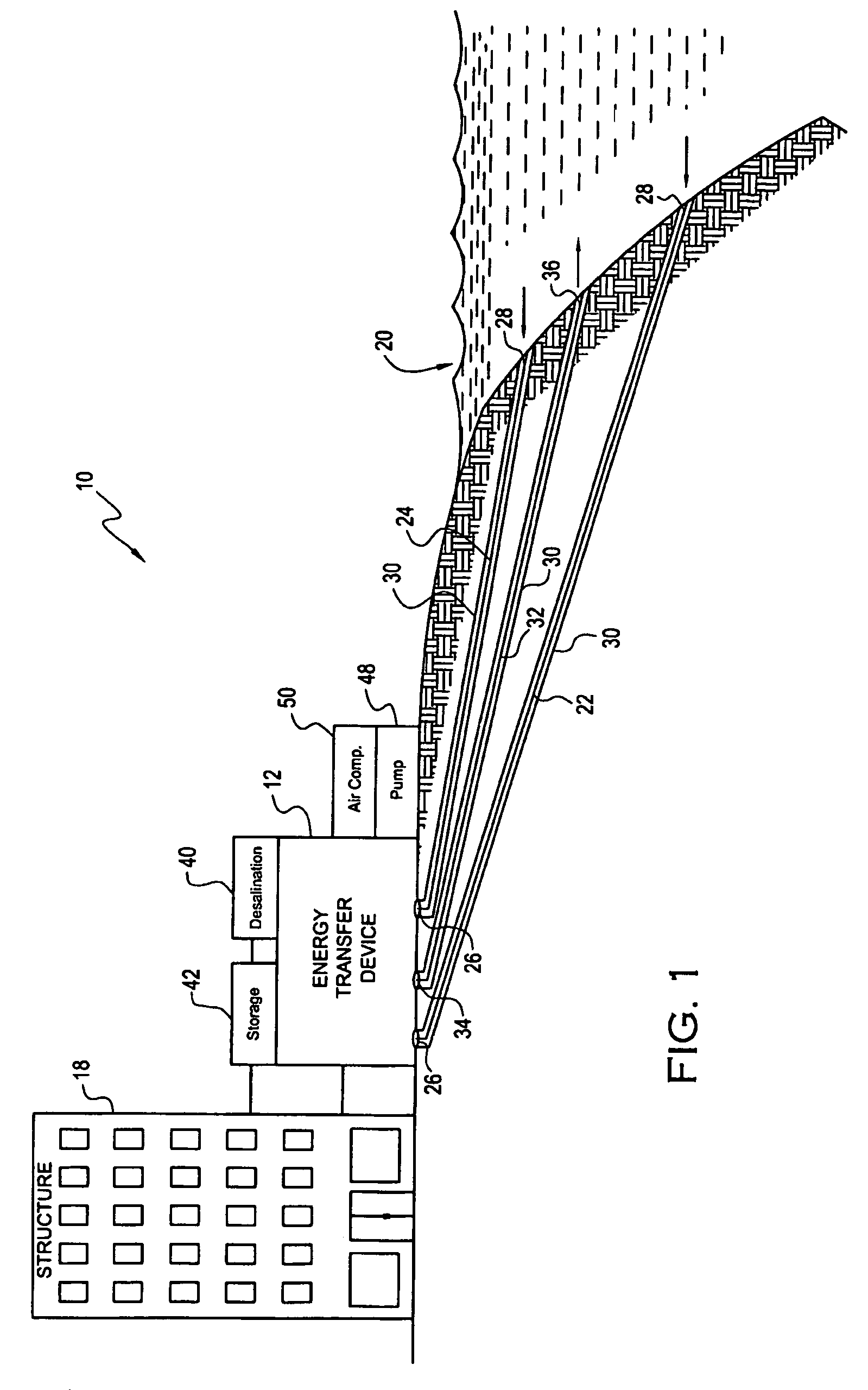
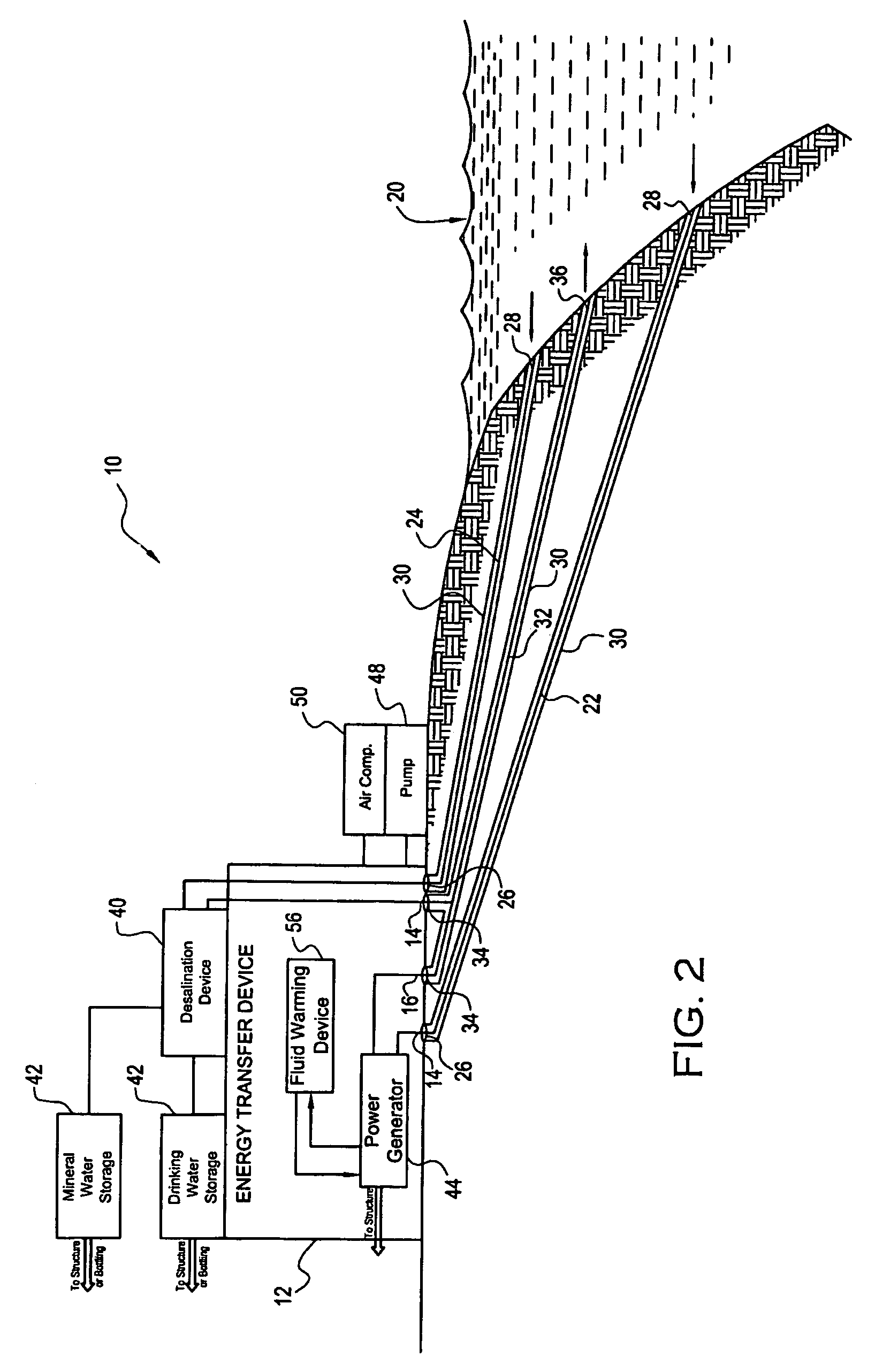
[0024]The present invention will now be described more fully hereinafter with reference to the accompanying drawings, in which preferred embodiments of the invention are shown. This invention may, however, be embodied in many different forms and should not be construed as limited to the embodiments set forth herein. Rather, these embodiments are provided so that this disclosure will be thorough and complete, and will fully convey the scope of the invention to those skilled in the art. Like numbers refer to like elements throughout.

[0025]Referring to FIGS. 1-3, an energy transfer system 10 according to the present invention is now described in greater detail. The energy transfer system illustratively includes an energy transfer device 12. The energy transfer device 12 includes water inlets 14, and a water outlet 16. Although one water outlet 16 is illustrated in the appended drawings, those skilled in the art will appreciate that any number of water outlets may be provided for the en...


PUM


Abstract

An energy transfer system includes an energy transfer device, a water inlet pipe and a water outlet pipe. The water inlet pipe may be connected to a water inlet of the transfer device to extract water from a water source. The water outlet pipe may be connected to a water outlet on the energy transfer device to discharge water to the water source. The water inlet pipe may extract water from a predetermined extraction depth, and the water outlet pipe may discharge water into the water source at a predetermined discharge depth.

Description

RELATED APPLICATIONS[0001]This application claims the benefit of U.S. Provisional Patent Application Ser. No. 60 / 717,506, filed on Sep. 15, 2005, and is related to U.S. patent application Ser. No. 11 / 532,287, titled Power Generation System and Associated Methods filed simultaneously herewith by the inventors of the present application, the contents of both of which are incorporated herein by reference in their entireties.FIELD OF THE INVENTION[0002]The present invention relates to the field of energy transfer and, more particularly, to the field of using temperature difference in a water source to transfer energy.BACKGROUND OF THE INVENTION[0003]Energy transfer systems that utilize temperature differences of adjacent water sources are known. These systems generally extract water from various depths of adjacent water sources to be used in heat exchange applications and power generation applications. The systems typically include pipes that are assembled above ground, and that must be...

Claims


Application Information

Patent Timeline
Patent Type & Authority Patents(United States)
IPC IPC(8): F28D3/00F24V50/00
CPCF03G7/04F04D29/329F24J2/465F24J2/242F24S10/72F24S80/70
Inventor JAGUSZTYN, TADEUSZ FRANKHAY, DONALD JAMESMURPHY, DON FRANKLIN
Owner COTHERM OF AMERICA CORP
Why Eureka
Try Eureka