
Locking random orbital dual-action head assembly

a technology of random orbital and head assembly, which is applied in the direction of power driven reciprocating saws, manufacturing tools, and carpet cleaners, etc., can solve the problems of reducing the functionality of the tool, reducing the size of the tool, and reducing the use of the tool by users wearing work gloves, so as to reduce the size, weight and cost of the locking device.

Inactive Publication Date: 2010-05-11
DYNABRADE
View PDF26 Cites 23 Cited by
  • Summary
  • Abstract
  • Description
  • Claims
  • Application Information

AI Technical Summary

Benefits of technology

[0018]A further object of the present invention is to minimize the size, weight, and cost of a locking random orbital dual-action head assembly.

Problems solved by technology

Furthermore, the circumferential slider comprises many components, increasing the cost of manufacturing and overall weight of the tool.
This broad incorporation restricts the capabilities of the tool.
Furthermore, the locking mechanisms, or spindle-locks, described in the references above can be awkward to manipulate by a user wearing work gloves.
Also, the locking mechanisms can be engaged accidentally by the user while the tool is in operation, resulting in excessive wear of the locking mechanism components and reducing the lifetime of the rotary tool and its components.

Method used


Image

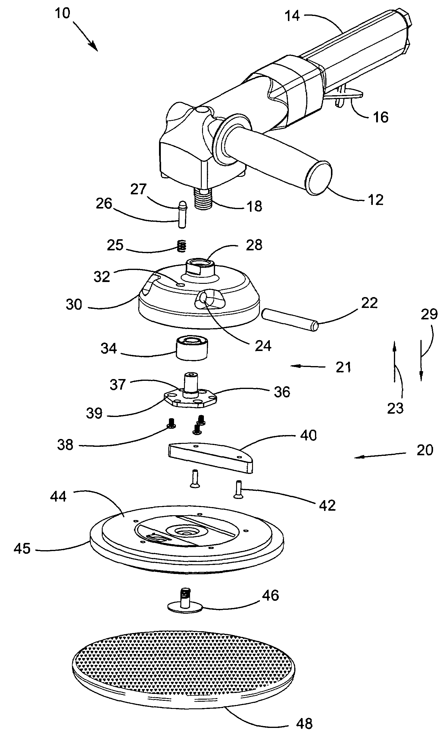
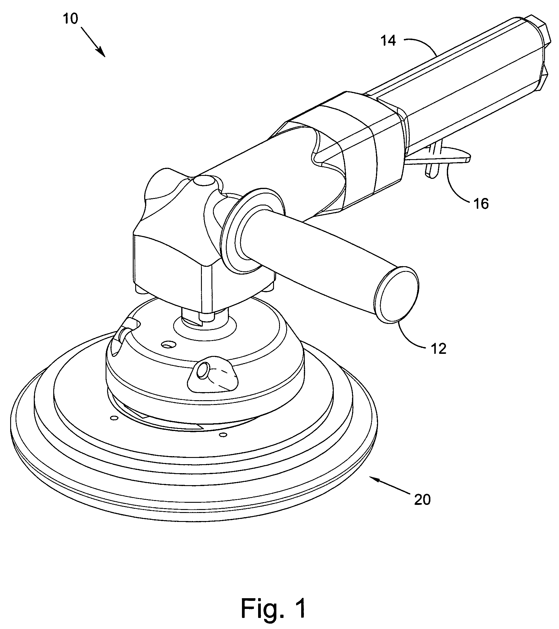
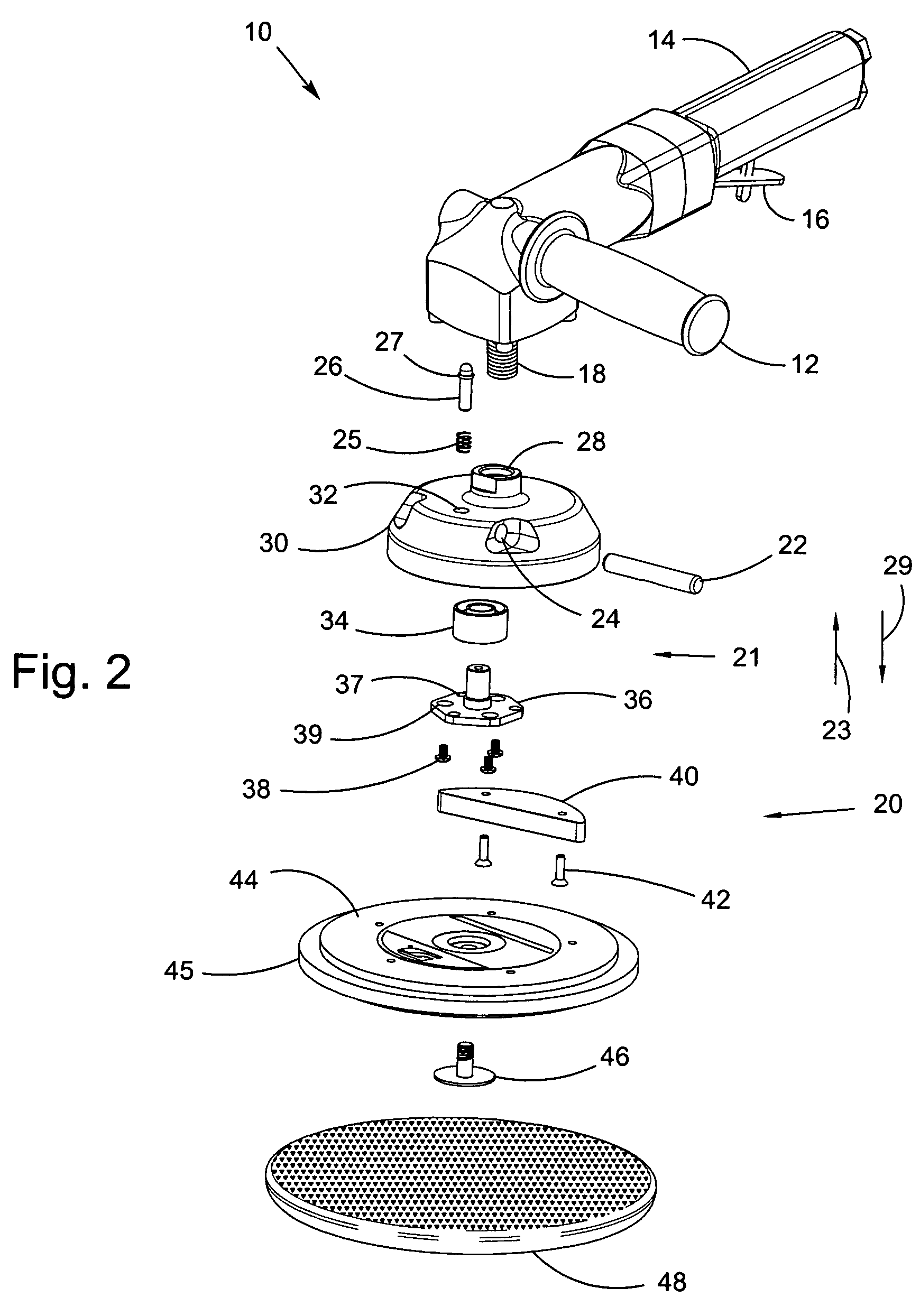
  • Locking random orbital dual-action head assembly
  • Locking random orbital dual-action head assembly
  • Locking random orbital dual-action head assembly

Examples


Embodiment Construction

[0030]At the outset, it should be appreciated that like drawing numbers on different drawing views identify identical, or functionally similar, structural elements of the invention. While the present invention is described with respect to what is presently considered to be the preferred aspects, it is to be understood that the invention as claimed is not limited to the disclosed aspects.

[0031]Furthermore, it is understood that this invention is not limited to the particular methodology, materials and modifications described and as such may, of course, vary. It is also understood that the terminology used herein is for the purpose of describing particular aspects only, and is not intended to limit the scope of the present invention, which is limited only by the appended claims.

[0032]Unless defined otherwise, all technical and scientific terms used herein have the same meaning as commonly understood to one of ordinary skill in the art to which this invention belongs. Although any meth...


PUM

PropertyMeasurementUnit
displacementaaaaaaaaaa
axis of rotationaaaaaaaaaa
weightaaaaaaaaaa

Abstract

A head assembly for a rotary tool, comprising a body arranged for connection to a drive means, the drive means rotatable about a first axis of rotation; a rotatable element arranged for connection to a pad assembly, the rotatable element rotatable about a second axis of rotation disposed substantially parallel to the first axis of rotation; and, a locking assembly arranged to lock the rotatable element to the body to prevent rotation of the rotatable element relative to the body about the second axis of rotation.

Description

FIELD OF THE INVENTION[0001]The present invention relates generally to a lockable random orbital dual-action head assembly. More particularly, the present invention relates to a locking assembly arranged to lock a rotatable element to prevent rotation of the rotatable element relative to the head assembly about an axis of rotation.BACKGROUND OF THE INVENTION[0002]Orbital abrading tools are well-known and generally comprise a portable, manually manipulatable housing, a motor supported by the housing and having or being coupled to a drive shaft driven for rotation about a first axis, and an assembly for mounting a pad for abrading or polishing a work surface for orbital movement about the first axis. In a random orbital abrading tool, the assembly serves to additionally mount the pad for free rotational movement about a second axis, which is disposed parallel to the first axis.[0003]The assembly typically includes a head portion coupled for driven rotation with the drive shaft about t...

Claims


Application Information

Patent Timeline
Patent Type & Authority Patents(United States)
IPC IPC(8): B24B23/02
CPCB24B23/022B24B23/03B24B23/028B24B23/00B24B23/02B24D3/00
Inventor LAMPKA, MARKGILES, MATTHEW A.
Owner DYNABRADE
Learn More