Method of evaluating the interaction between a wavefield and a solid body

a solid body and wavefield technology, applied in the field of methods, can solve the problems of increasing the size of computational domain, prohibitively expensive finite-difference simulations to run on even state-of-the-art computing equipment, and rarely performing full finite-difference migration, and achieve the effect of computational efficiency

Inactive Publication Date: 2010-05-11
WESTERNGECO LLC
View PDF6 Cites 60 Cited by
  • Summary
  • Abstract
  • Description
  • Claims
  • Application Information

AI Technical Summary

Benefits of technology

[0024]The present invention uses hence Green's function which include contribution of the wavefield scattered or reflected in the background but propagating back into an altered subspace. In scattering theories these part of the wavefield is usually referred to as second (or higher) order effects or multiples. It is seen as a particular advantage of the present invention that in the re-calculation of the wavefield in an altered model, higher-order scattering or multiples caused be the background are included. The preferred method of calculating Green's functions is the method described as interferometric in the above cited Phys. Rev. Lett. 94, 164301 (2005) and in the co-owned international patent application PCT / GB2005 / 003852.
[0025]When calculating an updated wavefield on the boundary, it is therefore not sufficient to restrict the methods to consider only the contribution of the wavefield on the extrapolation boundary as determined by the traveltime or by using (free-space) Green's function evaluated only at retarded values.
[0026]Instead, according to an aspect of the invention, the Green's function used extrapolate the contribution of the current wavefield from a point on the extrapolation surface to all future times or time steps at points on the boundary.
[0027]In a preferred embodiment the injection boundary is fully located inside the model space and thus does not form part of the boundary of the model space or the computational domain. It is seen as particular advantageous to place the injection boundary close to the extrapolation surface such that both, the extrapolation surface and the boundary enclose the updated sub-space.
[0028]According to another aspect of the invention, the model may include more than one subspace to be updated between model runs. Depending on the location and size of the subspaces, a single injection boundary can enclose more than one subspace. Alternatively each subspace may be enclosed by a corresponding injection boundary and Green's functions are used to propagate the wavefield from the extrapolation surface of one subspace to the injection boundaries enclosing the other subspaces. This approach can be computationally more efficient than enclosing a large volume of the model in a single injection boundary.
[0029]The Green's functions can also be used to extrapolate the wavefield between two arbitrary points in the full model domain. Preferably, Greens' functions are used to extrapolate a source signal or wavefield from a source location to an injection boundary or from an extrapolation surface to a receiver location.

Problems solved by technology

However, full finite-difference migration is rarely performed because of computational limitations restricting migration algorithms to the use of less accurate asymptotic techniques.
The common feature of these problems is that changes to the model are often restricted to a small sub-volume, but finite-difference simulations are required for the full model with several alterations.
However, as mentioned above, the finite-difference simulations tend to become prohibitively expensive to run on even state-of-the-art computing equipment.
However, even as an improvement over other known methods, the proposed method places still high demands on the performance of absorbing boundary conditions and significantly increases the size of computational domain (and thus the computational cost).

Method used


Image

  • Method of evaluating the interaction between a wavefield and a solid body
  • Method of evaluating the interaction between a wavefield and a solid body
  • Method of evaluating the interaction between a wavefield and a solid body

Examples


Embodiment Construction

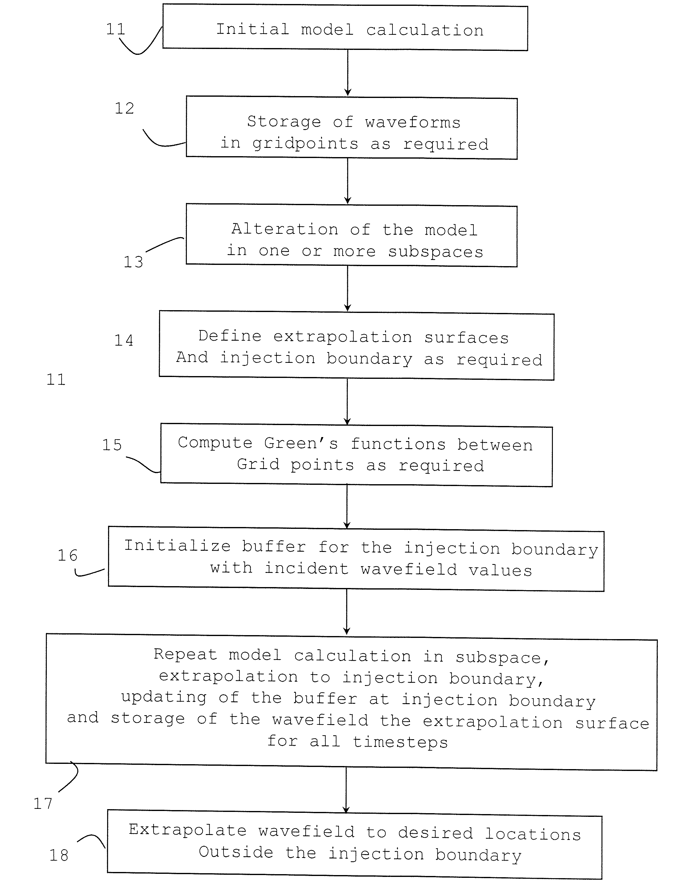
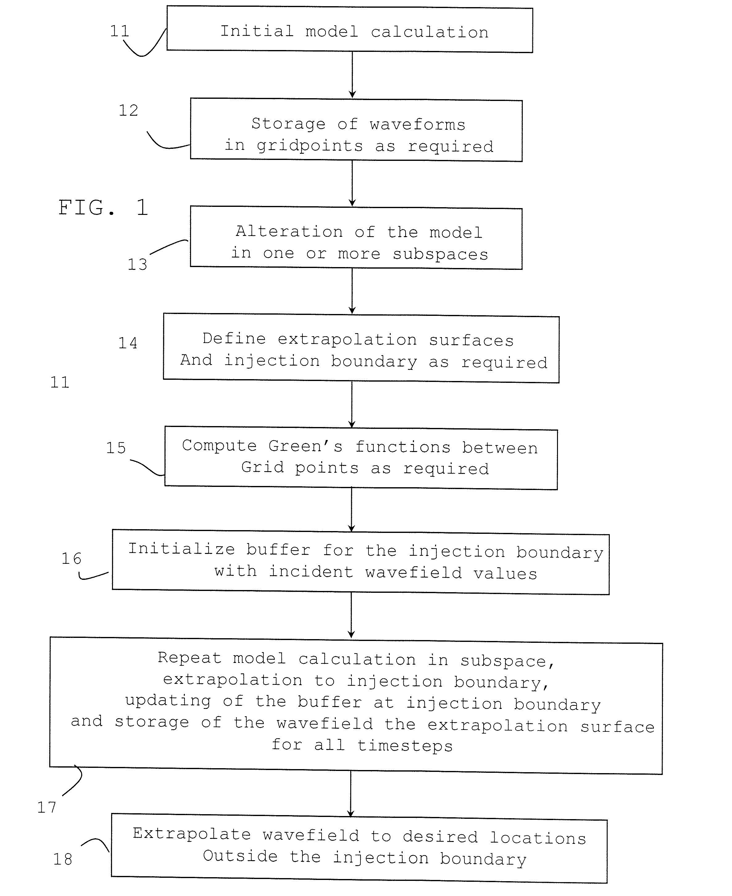
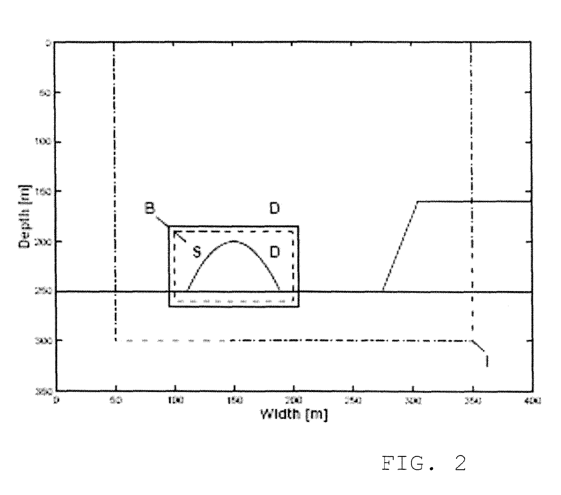
[0033]From general scattering theory, it is known that a representation for the scattered pressure at any point, xR, (x being a spatial vector) outside a surface Dsct surrounding the scatterer, can be derived from the values of the waveform on the surface using:

[0034]psct⁡(xR,t)=∫0t⁢∫¶⁢⁢Dsct⁢[Gq⁡(xR⁢|⁢x,τ-t)⁢vksct⁡(x,t)+Γkq⁡(xR⁢|⁢x,τ-t)⁢psct⁡(x,t)]⁢⁢υk⁢ⅆA⁢⁢ⅆt[1]

[0035]In eq. [1] the scattered wavefield {psct, vksct} is defined as the difference between the total wavefield {p, vk}, propagating in the perturbed model, and the incident wavefield {pinc, vkinc}, propagating in the background model and noting that both the incident and total wavefield are source free inside Dsct. The terms Gq(xR|x,τ−t) and Γkq(xR|x,τ−t) are the Green's function for pressure due to point sources of volume injection and body force, respectively, in the background medium.

[0036]Equation [1] can also be used to extrapolate the total wavefield because the incident wavefield is source free in the region of the pe...


PUM


Abstract

Described is a finite-difference methodology for efficiently computing the response from a model subject to changes within sub-volumes with the sub-volume enclosed with an extrapolation surface within an injection boundary using Green's functions to update the injection boundary and transmitting an updated wavefield from the injection boundary back into the altered sub-volume to include higher order reflections from outside of the altered sub-space.

Description

[0001]The present invention relates to methods of determining the response caused by alterations of a model in simulations of wave propagation. More specifically, it relates to determining the seismic response caused by model alterations in finite-difference (FD) simulations.BACKGROUND OF THE INVENTION[0002]A wide variety of modeling, processing and inversion algorithms require the recalculation of the response after local alterations to an initial model. For example, pre-stack finite-difference migration of seismic data provides a highly accurate means of producing images of the Earth's interior. The migration algorithm consists of recalculating the finite-difference response of small local changes to the seismic model. However, full finite-difference migration is rarely performed because of computational limitations restricting migration algorithms to the use of less accurate asymptotic techniques. Another example relates to finite-difference inversion, where recalculating the fin...

Claims


Application Information

Patent Timeline
Patent Type & Authority Patents(United States)
IPC IPC(8): G01V1/00G06G7/56
CPCG01V1/28G01V2210/57G01V1/282G06F30/23
Inventor VAN MANEN, DIRK-JANROBERTSSON, JOHANCURTIS, ANDREW
Owner WESTERNGECO LLC
Why Eureka
Try Eureka