Magnetic plate for printing of optical effects

a technology of optical effects and magnetic plates, applied in the field of magnetic plates for printing optical effects, can solve the problems of poor color-shifting effect, essentially useless utilization of magnetic color-shifting inks for secure document printing,

Active Publication Date: 2010-05-18
VIAVI SOLUTIONS INC
View PDF28 Cites 11 Cited by
  • Summary
  • Abstract
  • Description
  • Claims
  • Application Information

AI Technical Summary

Problems solved by technology

For example when using color-shifting inks, a very poor color-shifting effect resulted.
Color-shifting properties by the images printed with the device described in EP 1 493 590 makes utilization of magnetic color-shifting inks for the printing of secure documents essentially useless.

Method used


Image

  • Magnetic plate for printing of optical effects
  • Magnetic plate for printing of optical effects
  • Magnetic plate for printing of optical effects

Examples


Embodiment Construction

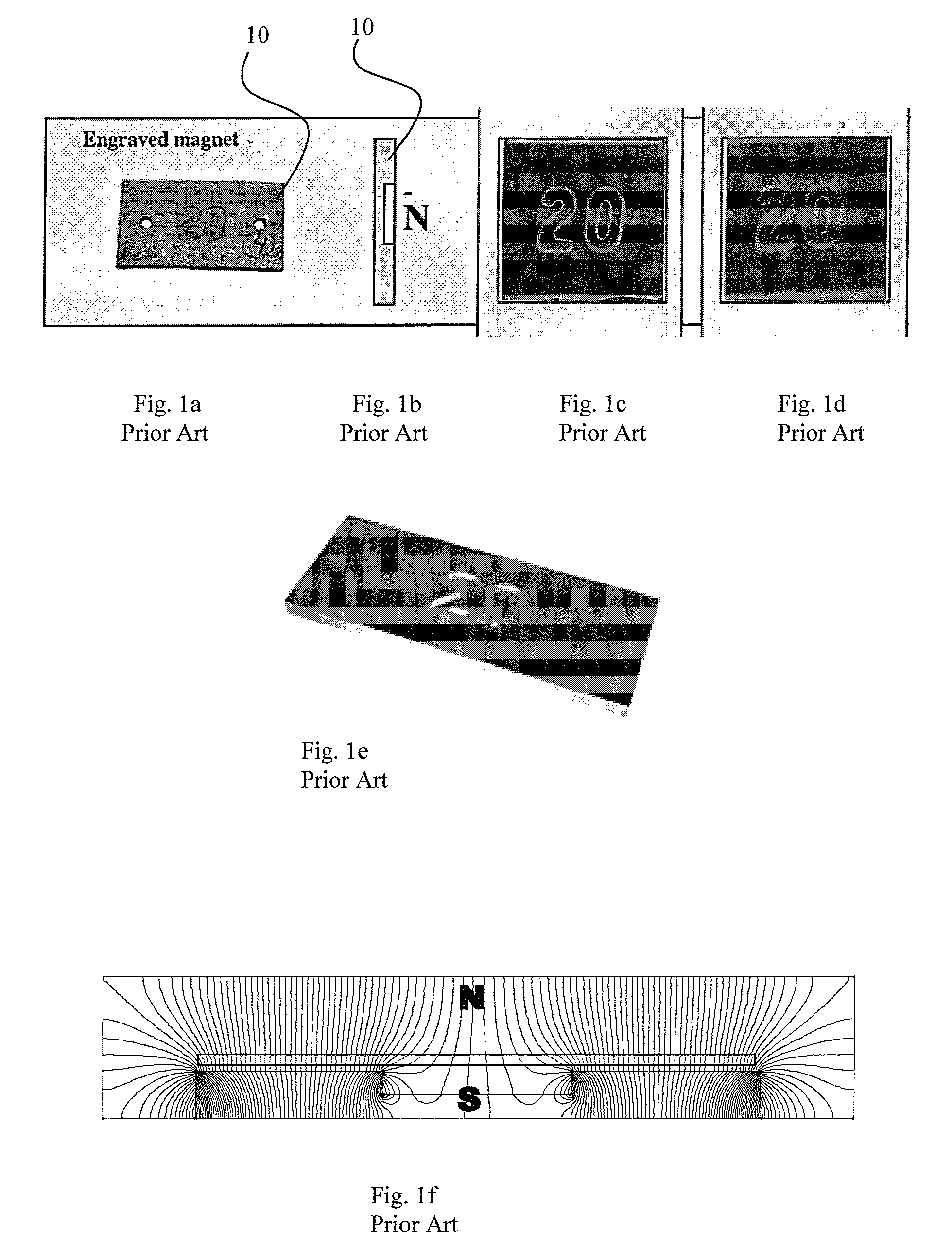
[0077]Referring now to prior art FIGS. 1a through 1f, an engraved magnet is shown in FIG. 1a which is used to form a print within a substrate coated with wet ink or paint containing magnetically alignable particles or flakes. After a substrate is coated with the ink or paint the magnet 10 is placed under the substrate and the flakes within the ink or paint align along the field lines forming the numeral 20. In FIG. 1c, reflective flakes, for example Ni, having a silver-like appearance in a blue carrier vehicle are aligned to form the numeral 20. The flakes appear to take on the color of the die and flakes within the background of the “20” and within the numerals themselves have a dark appearance. This is because the flakes are upstanding and all that can be seen is the dark blue carrier vehicle in the spaces between the upstanding flakes. A similar effect is illustrated in FIG. 1d where color shifting flakes are used. The magnetic field in FIG. 1f emanating from the engraved magnet ...


PUM

PropertyMeasurementUnit
magnetic fieldaaaaaaaaaa
magnetizableaaaaaaaaaa
soft magneticaaaaaaaaaa

Abstract

This invention discloses a magnet for use as a printing plate or printing head that is used for aligning flakes or particles in a paint or ink. A composite sheet or block of magnetizable material is selectively magnetized so that a magnet is formed within the sheet or block that has a shape of a predetermined image, logo, or indica. Dies are used to magnetize the magnetizable material and preferably the does contact the material to be magnetized. A pre-magnetized sheet such as a refrigerator magnet may be re-magnetized differently so that a magnetic image is encoded therein for use as a printing plate. Preferably the printing plate is flexible so that it can be formed to a curved surface of a cylinder or drum for printing. Conveniently these flexible magnets can be changed for other designs and placed on the same drum for use in printing.

Description

CROSS-REFERENCE TO RELATED APPLICATIONS[0001]The present invention claims priority from U.S. patent application Ser. No. 60 / 737,926 filed Nov. 18, 2005, which is incorporated herein by reference for all purposes.FIELD OF THE INVENTION[0002]This invention relates generally to a magnet for use in printing inks and paints with magnetically alignable particles or flakes, and more particularly relates to forming magnets which have magnetic material aligned in a plurality of different directions in accordance with an applied field and to the use of these magnets as printing plates.[0003]The term “sheet” is used hereafter within this specification to mean a flat thin sheet, and in preferred embodiments as a flexible sheet; however the term sheet is not limited thereto.[0004]The term “plate” used throughout this specification is to mean a stiff or a flexible plate and is to include thin, flat flexible sheet, such as a composite magnetizable sheet or as a rubber magnetic sheet more commonly ...

Claims


Application Information

Patent Timeline
Patent Type & Authority Patents(United States)
IPC IPC(8): B41C3/08B41G7/00B41N6/00H01F1/00H01F3/00H01F7/00
CPCB05D3/207B05D5/06B41C1/00B41N1/04G11B5/855H01F13/003B41C1/1058B05D3/14B05D3/06
Inventor RAKSHA, VLADIMIR P.HOLMAN, JAY M.COOMBS, PAUL G.TEITELBAUM, NEILMARKANTES, CHARLES T.
Owner VIAVI SOLUTIONS INC
Why Eureka
Try Eureka