Chair

a chair and frame technology, applied in the field of chairs, can solve the problems of not allowing the upper portion of the upper body to be stably supported, and the sitter feels insecure, and achieve the effect of reducing the sitter's stress

Inactive Publication Date: 2010-05-18
KOKUYO CO LTD
View PDF93 Cites 76 Cited by
  • Summary
  • Abstract
  • Description
  • Claims
  • Application Information

AI Technical Summary

Benefits of technology

[0009]Here, the present invention includes an aspect in which the elastically biasing force to the upper frame portion becomes weaker as the lower frame portion is tilted rearward, and an aspect in which the elastically biasing force to the upper frame portion becomes stronger.
[0010]With the above-described constitution, the elastically biasing force to the upper frame portion can be set in accordance with a posture of a sitter, particularly, a posture of the upper body. That is, in the case where a shape of a backrest of the chair is desired to follow the motion of the upper body of the sitter, the elastically biasing force to the upper frame portion is set weaker, and in the case where the upper body of the sitter is desired to be supported by the backrest, the elastically biasing force to the upper frame portion can be set stronger. As a result, the chair having the backrest serving differently in accordance with the posture of the sitter, particularly the posture of the upper body, can be provided.
[0013]As a more specific constitution in the former case, a constitution can be cited in which the elastic member is made of a torsion coil spring, whose one end side and another end side are locked in the upper frame portion and the lower frame portion, by which there is provided repulsive force changing means capable of changing an initial repulsive force of the torsion coil spring by changing a locking position of the torsion coil spring as the lower frame portion becomes closer to the rearward tilting position. The above-described constitution allows the upper frame portion biasing means to be provided compactly in a portion between the upper frame portion and the lower frame portion.
[0020]According to the present invention, in the case where the shape of the backrest of the chair is desired to follow the motion of the upper body of the sitter, the elastically biasing force of the upper frame portion is set weaker, and in the case where the upper body of the sitter is desired to be supported by the backrest, the elastically biasing force to the upper frame portion can be set stronger. As a result, it can be provided a chair having a backrest serving in accordance with the posture of the sitter.

Problems solved by technology

That is, the elastically biasing force of such a degree that the upper frame elements of the backrest can move in accordance with the motion of the upper body of the sitter as described above does not allow the upper portion of the upper body to be stably supported.
In such a chair, there may arise a defect that when the sitter inclines his or her upper body by tilting the lower frame elements of the backrest rearward, the sitter feels insecure.

Method used


Image

  • Chair
  • Chair
  • Chair

Examples


first embodiment

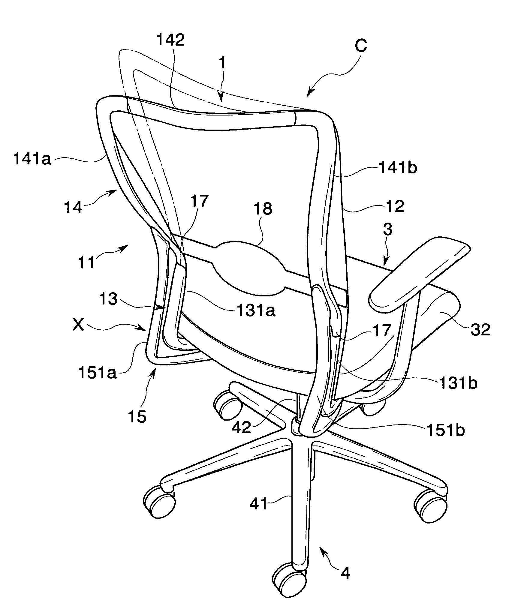
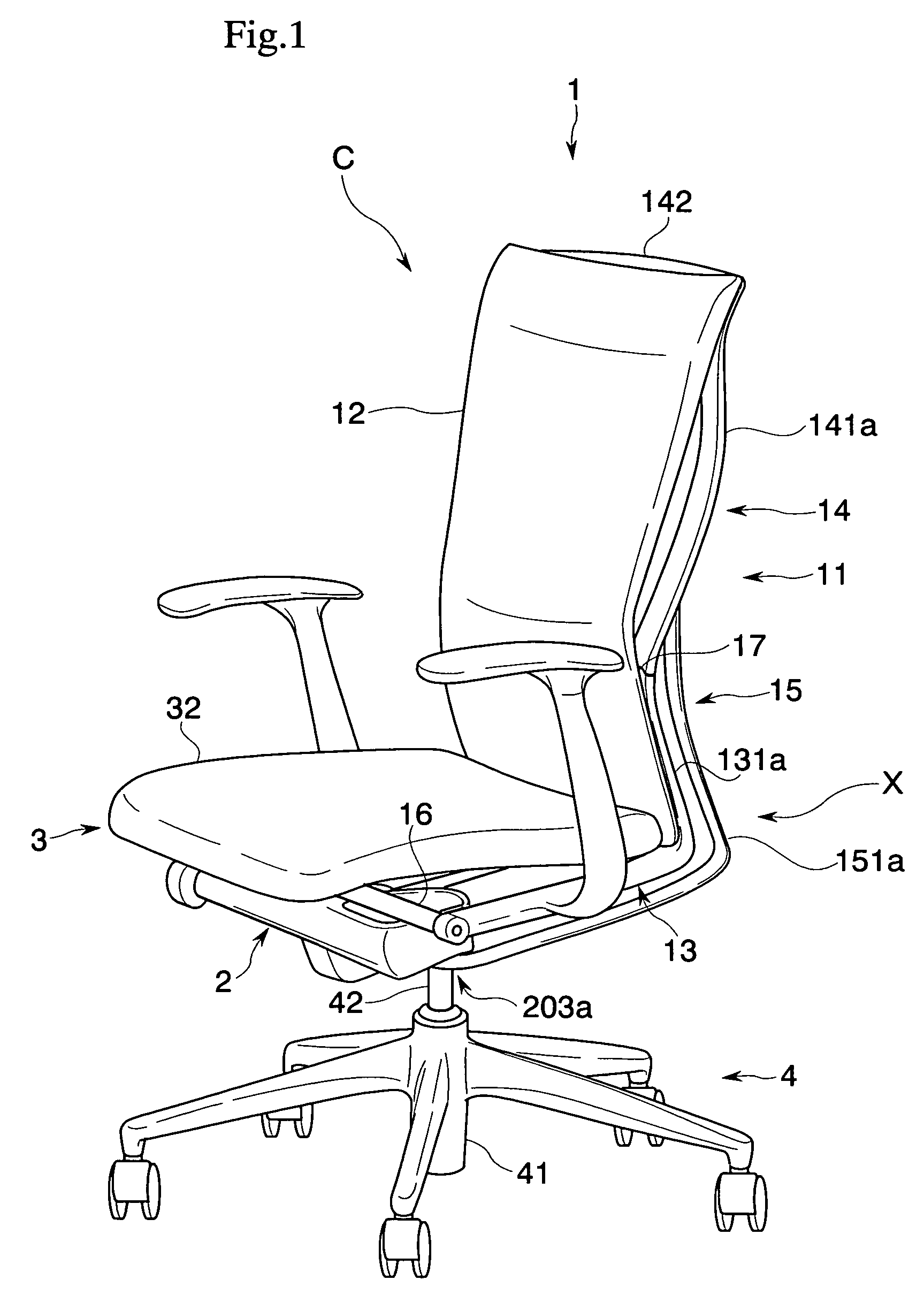
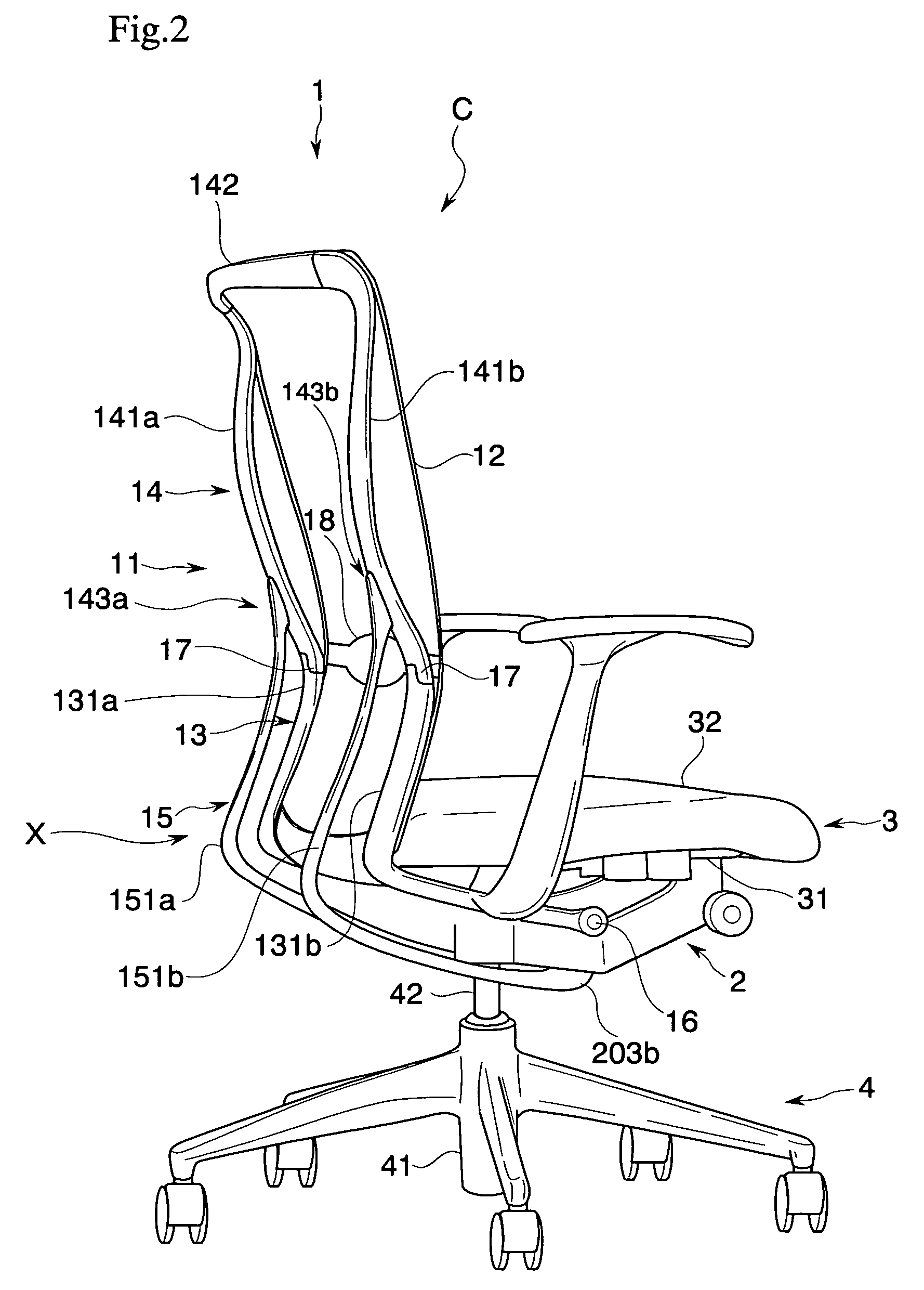
[0043]A first embodiment of the present invention is described with reference to the drawings. A chair C of the present embodiment, as shown in FIGS. 1 to 5, includes a leg body 4, a base 2 supported by the leg body 4, a seat 3 arranged on the base 2, and a backrest 1 attached to the base 2 pivotally through a horizontal shaft 16, and is capable of synchronous rocking movement in which the seat 3 and the backrest 1 are interlocked and tilted rearward.

[0044]In this case, the chair C according to the present embodiment includes a lower frame portion 13 supported so as to be capable of rocking between a standing position (S) and a rearward tilting position (T) with respect to the base 2, and an upper frame portion 14 supported so as to be capable of rocking between a normal position (N) and a rear end position (E) with respect to the relevant lower frame portion 13. Furthermore, upper frame portion biasing means X that elastically biases the upper frame portion from the rear end portio...

second embodiment

[0071]A chair C2 according to a second embodiment of the present invention, as shown in FIGS. 10 to 15, is constituted such that upper frame portion biasing means X1 is made of a torsion coil spring 17sp, which is an elastic member, provided between the above-described upper frame portion 14 and lower frame portion 13, and includes repulsive force changing means X11, described later, that can change an initial repulsive force of the torsion coil spring 17sp by changing a locking position of the relevant torsion coil spring 17sp. Furthermore, a regulator 19 is mounted to provide a movement range setting mechanism A that can change a movement range of the upper frame portion 14 corresponding to the position of the lower frame portion 13.

[0072]Hereinafter, a constitution of the chair C2 according to this embodiment is described.

[0073]The regulator 19, as shown in FIGS. 10 to 12, has regulating members 191a, 191b and link elements 192a, 192b. The regulator 19 forms a substantially-L-sha...

third embodiment

[0087]Next, a chair C3 according to a third embodiment of the present invention is described.

[0088]In the chair C3 according to the present embodiment, as shown in FIGS. 18, 19, upper frame portion biasing means X2 is made up by providing the reactive force frame portion 15 made of reactive force frame elements A151a, A151b, which are resin springs, between the upper frame portion 14 and the lower frame portion 13, as an elastic member. Further, there is provided supporting position changing means Y1 capable of changing a supporting position where the reactive force frame elements A151a, A151b are supported, corresponding to the rocking movement of the lower frame portion 13. As a specific constitution of the supporting position changing means Y1, various mechanisms or structures such as position change by gear or position change employing a link mechanism can be employed.

[0089]With the above-described mechanisms or structures, the elastic repulsive force can preferably be applied t...


PUM


Abstract

There is provided a chair that realizes a state preferably following a motion of a sitter in accordance with a posture of the relevant sitter, and a state preferably supporting the sitter. The chair includes a lower frame portion supported so as to be capable of rocking between a standing position and a rearward tilting position with respect to a base, and an upper frame portion supported so as to be capable of rocking between a normal position and a rear end position with respect to the relevant lower frame portion. Furthermore, upper frame portion biasing that elastically biases the upper frame portion from the rear end position to the normal position is provided. This upper frame portion biasing is adapted to change an elastically biasing force to the upper frame portion corresponding to a position in the rocking movement of the lower frame portion.

Description

BACKGROUND OF THE INVENTION[0001]1. Field of the Invention[0002]The present invention relates to a chair whose backrest can be tilted rearward.[0003]2. Description of the Related Art[0004]Conventionally, there has been disclosed a chair in which a backrest surface is made up by extending an upholstery member between frame elements, which make a pair on both right and left sides. For example, there has been disclosed a chair employing a structure in which an upper portion of the backrest surface is supported by upper frame elements and a lower portion of the backrest surface is supported by lower frame elements, and these upper frame elements and lower frame elements are made independent to perform rotational operation around a horizontal axis, that is, rocking movement (for example, refer to Japanese Patent Application Laid-Open No. 2002-119375 and Japanese Patent Application Laid-Open No. 2002-119373). Furthermore, in the chair having such a constitution, by providing elastically b...

Claims


Application Information

Patent Timeline
Patent Type & Authority Patents(United States)
IPC IPC(8): A47C3/00
CPCA47C7/443A47C7/444
Inventor UEDA, NOBUYUKI
Owner KOKUYO CO LTD
Why Eureka
Try Eureka