Frame for speaker device and speaker device

a speaker device and frame technology, applied in the direction of transducer details, electrical transducers, electrical apparatus casings/cabinets/drawers, etc., can solve problems such as distortion of sound quality, and achieve the effect of preventing frame distortion, improving frame strength, and deteriorating sound quality

Inactive Publication Date: 2010-05-18
PIONEER CORP +2
View PDF9 Cites 7 Cited by
  • Summary
  • Abstract
  • Description
  • Claims
  • Application Information

AI Technical Summary

Benefits of technology

[0010]The present invention has been achieved in order to solve the above problems. It is an object of this invention to provide a frame for a speaker device and a speaker device using the frame capable of improving the strength of the frame and preventing distortion of the frame and deterioration of sound quality by designing the frame in consideration of an organic association (regularity) of plural arm portions and mounting portions provided on a mounting base.
[0012]In the above-mentioned frame for the speaker device, the pair of the plural arm portions connecting the magnetic circuit housing unit and the outer peripheral portion are linearly positioned to form the bridges connecting the two parts of the outer peripheral portion. Namely, the plural arm portions form the plural bridges. The plural bridges are formed at the position which does not pass through the center of the outer peripheral portion and serve as reinforcement members against stress applied to the outer peripheral portion from the outer side. Thereby, the strength of the frame is enhanced.
[0013]In a manner of the above frame, the plural bridges may include at least first and second bridges, and the first and second bridges may be arranged at positions corresponding to sides of a triangle inscribed in the outer peripheral portion. In this manner, the triangle inscribed in the outer peripheral portion, including the two bridges, reinforces the annular outer peripheral portion from the inner side, and the strength of the frame is securely improved.
[0014]In a preferred example of the above frame, the outer peripheral portion may have plural mounting portions provided on a mounting base, and both ends of the first and second bridges may be arranged at positions corresponding to the plural mounting portions. Since the plural mounting portions are fixed to the mounting base such as a mounting panel of a vehicle, by making both ends of the bridge correspondent to the mounting portion, the bridge can more securely improve the strength of the frame.
[0016]In still another preferred example of the above frame, the plural mounting portions may include first to third mounting portions; the first mounting portion may be arranged at a position corresponding to 12 o'clock in a clockwise direction, the second mounting portion may be arranged at a position corresponding to 3 to 6 o'clock in the clockwise direction, and the third mounting portion may be arranged at a position corresponding to 6 to 9 o'clock in the clockwise direction, respectively, when the outer peripheral portion is planarly observed; ends of the first and second bridges may be arranged at a position corresponding to the first mounting portion, respectively; another end of the first bridge may be arranged at a position corresponding to the third mounting portion, and another end of the second bridge may be arranged at a position corresponding to the second mounting portion, respectively. Thereby, the strength of the frame can be improved against the stress in any directions of the outer peripheral portion.
[0017]In a preferred example in this case, the first bridge may be positioned on a line connecting the first mounting portion and the third mounting portion, and the second bridge may be positioned on a line connecting the first mounting portion and the second mounting portion. Since the plural mounting portions are fixed to the mounting base such as a mounting panel of the vehicle, by making both ends of the bridge correspondent to the mounting portion, the bridge can more securely improve the strength of the frame.

Problems solved by technology

However, the plural arm portions and the mounting portions arranged at the outer peripheral portion of the frame are not designed to have an organic association (regularity).
Thereby, the frame is problematically distorted, which easily causes distortion of sound quality.

Method used


Image

  • Frame for speaker device and speaker device
  • Frame for speaker device and speaker device
  • Frame for speaker device and speaker device

Examples


Embodiment Construction

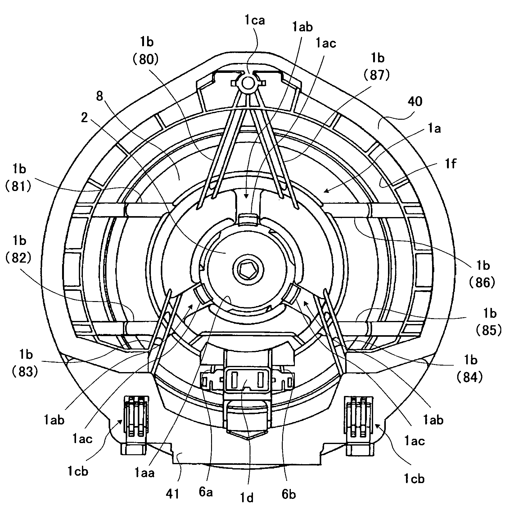
[0027]The preferred embodiments of the present invention will now be described below with reference to the attached drawings. In this embodiment, by designing the frame in consideration of the organic association (regularity) of the plural arm portions and the mounting portions provided on the mounting base, the strength of the frame is enhanced, and the distortion of the frame is prevented. Thereby, the deterioration of the sound quality is prevented.

[Configuration of Speaker Device]

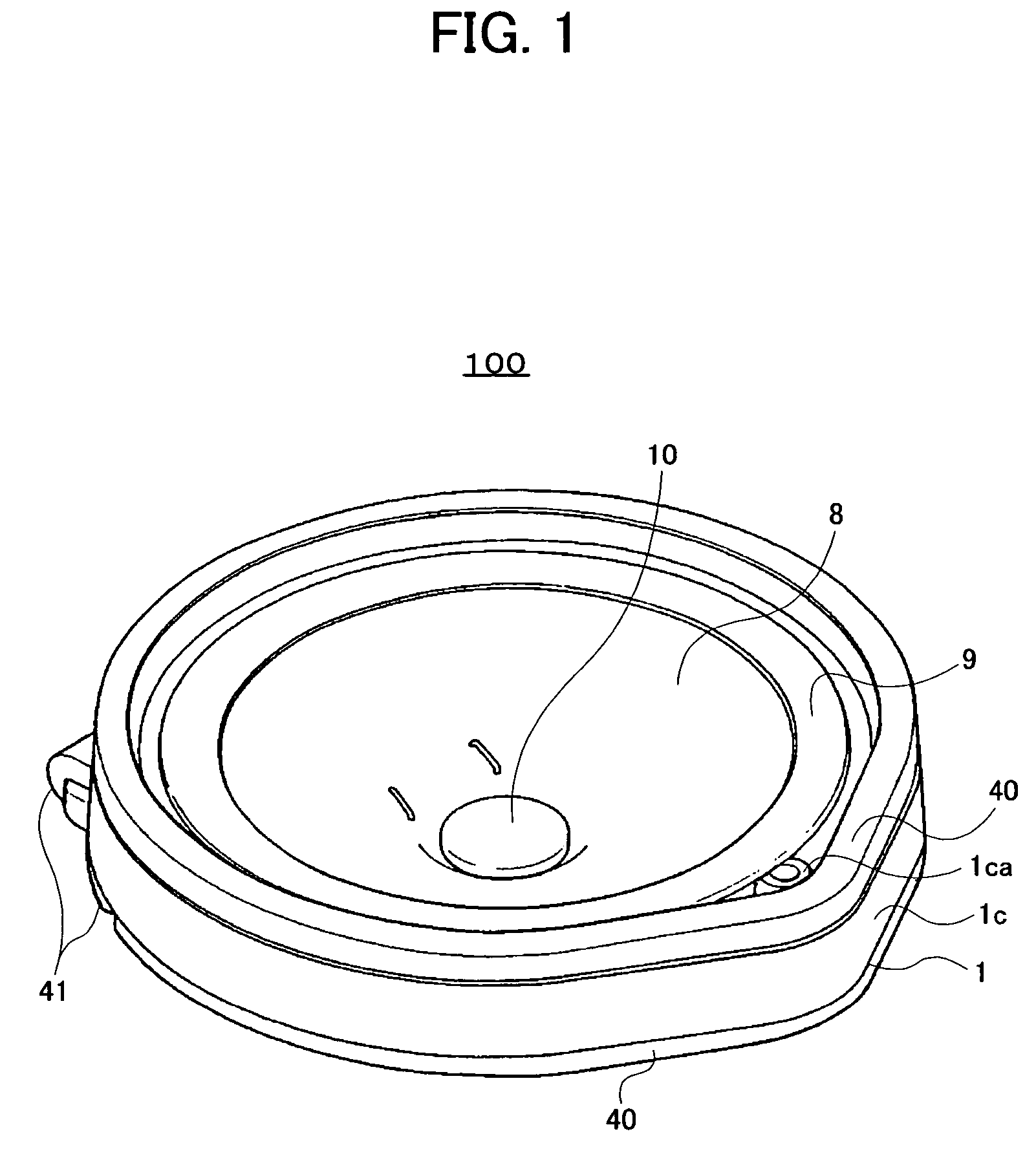
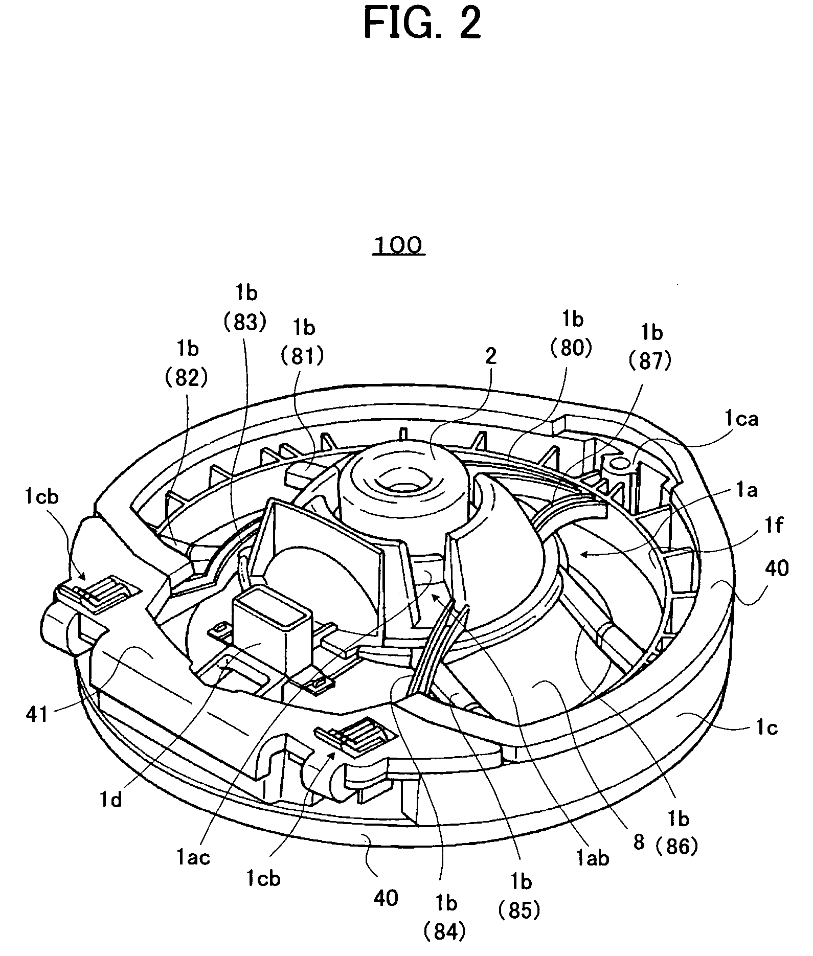
[0028]First, a description will be given of a configuration of a speaker device 100 according to an embodiment of the present invention with reference to FIG. 1 to FIG. 5.

[0029]FIG. 1 shows a perspective view of the speaker device 100 according to an embodiment of the present invention in a case that it is observed from its sound output side. FIG. 2 shows a perspective view of the speaker device 100 in a case that it is observed from a side opposite to the sound output side, i.e., from a rear side. FIG....


PUM


Abstract

A frame for a speaker device includes a magnetic circuit housing unit which houses a magnetic circuit, an annular outer peripheral portion which is arranged on an outer side of the magnetic circuit housing unit, and plural arm portions which connect the magnetic circuit housing unit and the outer peripheral portion. The plural arm portions form such plural bridges that a pair of the arm portions are linearly positioned to connect two parts of the outer peripheral portion, and each of the bridges does not pass through a center of the outer peripheral portion.

Description

BACKGROUND OF THE INVENTION[0001]1. Field of the Invention[0002]The present invention relates to a configuration of a frame for a speaker device.[0003]2. Description of Related Art[0004]Conventionally, there is known a speaker device including a vibrating system having a frame and a diaphragm, and a magnetic circuit system having a yoke, a magnet and a plate.[0005]In such a speaker device, the frame is formed into a bowl shape, for example. The frame having such a shape includes a magnetic circuit housing unit holding a magnetic circuit, an outer peripheral portion disposed on an outer side of the magnetic circuit housing unit and having an edge mounting portion on which an outer peripheral portion of an edge is mounted, and plural arm portions connecting the magnetic circuit housing unit and the outer peripheral portion.[0006]Particularly, on the frame having such a configuration, the plural arm portions are provided to radially extend from a center of the frame to the outer periph...

Claims


Application Information

Patent Timeline
Patent Type & Authority Patents(United States)
IPC IPC(8): H04R25/00
CPCH04R9/06H04R2400/11H04R2201/34
Inventor SASAKI, HIROMITSUMORIYAMA, YUTAKASAKAGUCHI, EIJIOKI, HIDEHITOHARANO, TSUTOMUSODA, MASAKIAIZAWA, NOBUOMATSUO, RYOJI
Owner PIONEER CORP
Why Eureka
Try Eureka