Sink with removable divider

a technology of dividers and sinks, applied in the field of dividers with removable dividers, can solve the problems of not providing a mechanism for sealing and unsealing the dividers or the design of sinks that does not provide for selectively and conveniently removable dividers, etc., and achieves the effect of convenient us

Inactive Publication Date: 2010-05-25
MARTIN KENNETH W +1
View PDF6 Cites 31 Cited by
  • Summary
  • Abstract
  • Description
  • Claims
  • Application Information

AI Technical Summary

Benefits of technology

[0005]The sink includes an electromagnet positioned beneath the bottom surface of the sink and the divider includes a complementary ferrous material. Accordingly, the ferrous material of the divider is magnetically attracted to the electromagnet when the electromagnet is actuated. This enables the divider to be held tight against the bottom surface of the sink to prevent leakage of water between the now-separate compartments. Channels defined by the side wall of the sink guide the divider into position and ensure flush alignment with the bottom surface of the sink. Gaskets may also be positioned about the divider for a watertight fit when the electromagnet is activated. A sensor may also be included for activating the electromagnet automatically upon detection of a predetermined condition such as the pressure of the divider against the bottom of the sink.
[0007]Another object of this invention is to provide a sink, as aforesaid, in which the divider may be efficiently inserted into or removed from the sink basin.
[0009]Yet another object of this invention is to provide a sink, as aforesaid, that is easy and convenient to use.

Problems solved by technology

Although assumably effective for their intended purposes, these sink designs do not provide for a selectively and conveniently removable divider or do not provide a mechanism for sealing and unsealing the divider.

Method used


Image

  • Sink with removable divider
  • Sink with removable divider
  • Sink with removable divider

Examples


Embodiment Construction

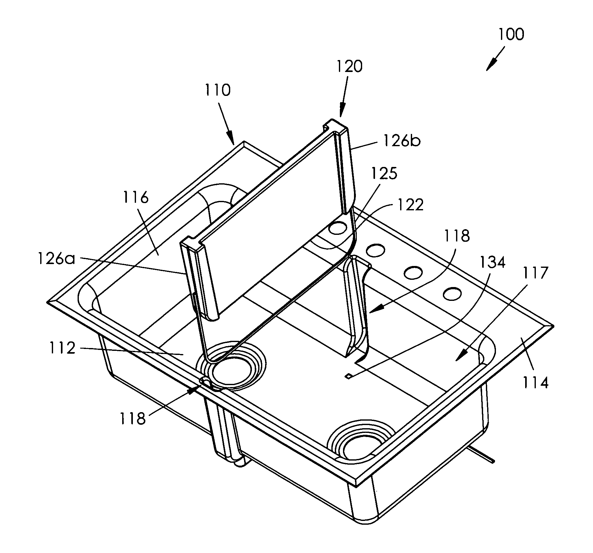
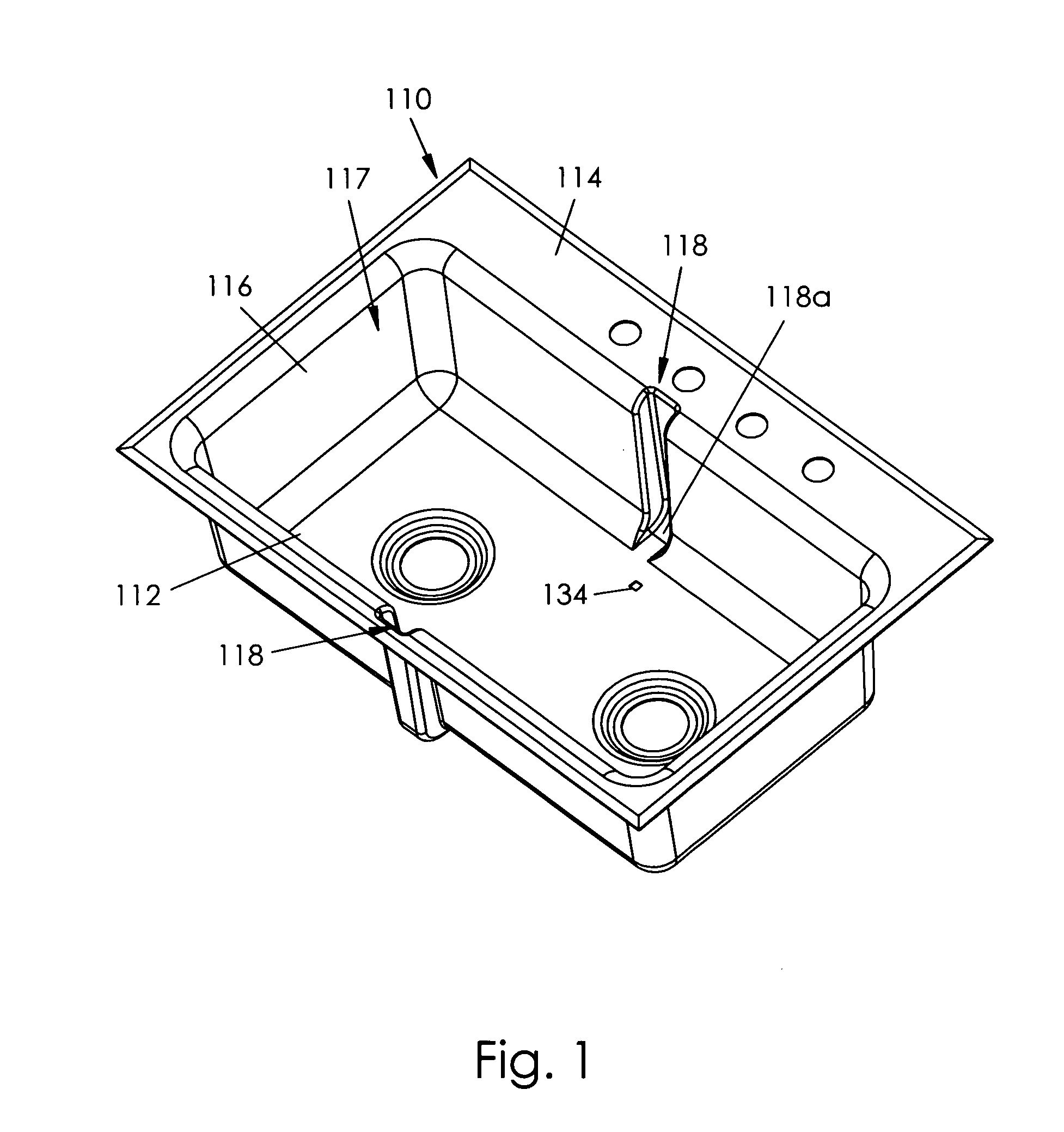
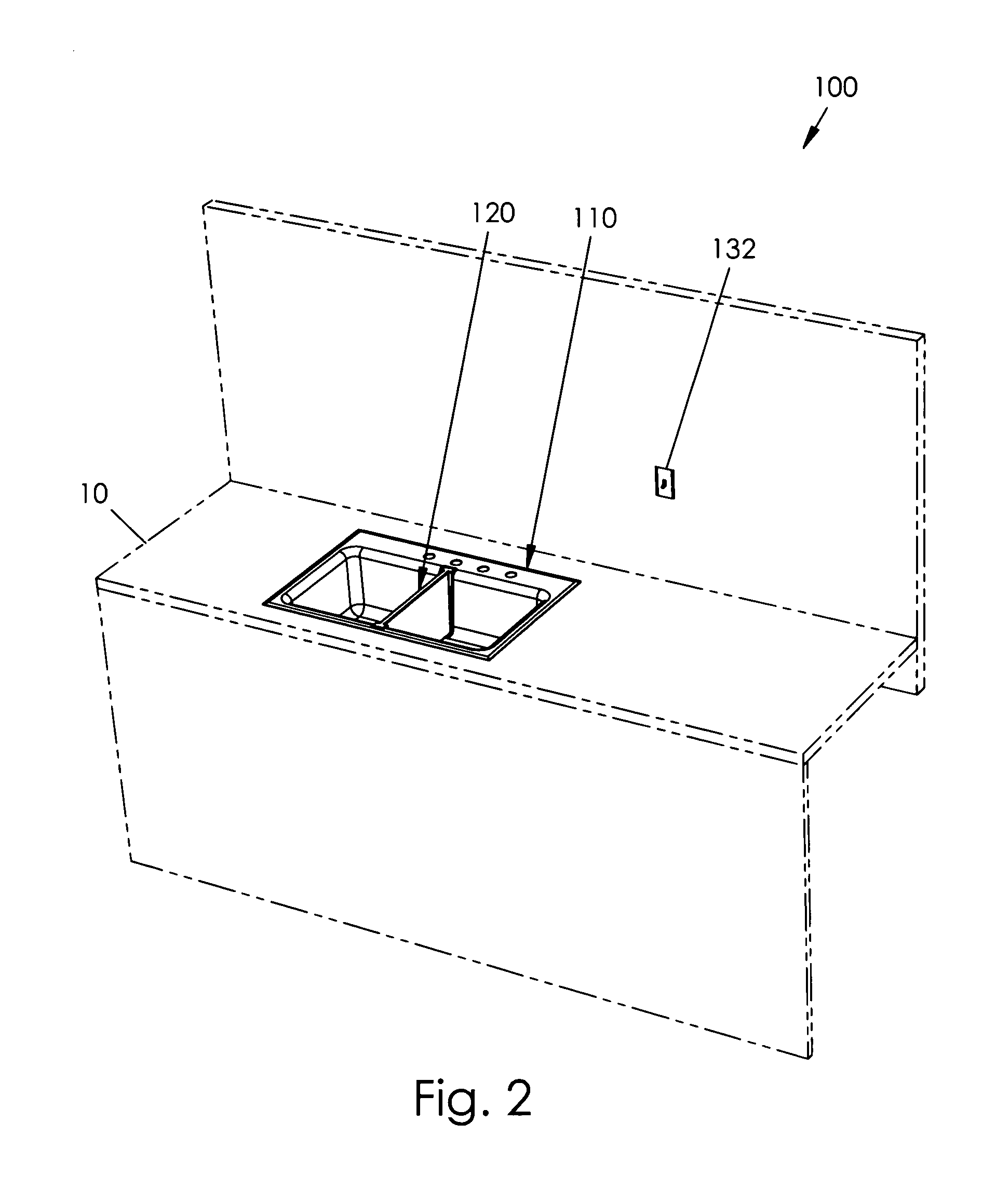
[0019]A sink 100 according to the present invention will now be described in detail with reference to FIGS. 1 through 7 of the accompanying drawings. More particularly, a sink 100 according to the current invention includes a basin 110, a divider 120, and an electromagnet 130.

[0020]The basin 110 presents a bottom surface 112 spaced apart from a top surface 114. At least one sidewall 116 connects the bottom and top surfaces 112, 114 to define an interior area 117 between the bottom surface 112, the top surface 114, and the at least one sidewall 116. If only one sidewall 116 is used, the basin 110 may be oval or round, for example; if more than one sidewall 116 is used, the basin 110 may be rectangular, octagonal, or other various shapes. The sidewall(s) 116 may define opposed channels 118, as shown throughout the drawings, and the channels 118 may have rounded lower corners 118a.

[0021]The divider 120 is sized to be received in the basin interior area 117 to partition the basin inter...


PUM


Abstract

A sink according to the present invention includes a sink basin having a bottom surface and a top surface with at least one side wall extending therebetween. The sink includes a divider that may be inserted into or removed from an interior area of the sink for selectively dividing the basin into multiple smaller compartments. An electromagnet is positioned beneath the bottom surface of the sink and is attracted to a ferrous material on the bottom of the divider for holding the divider securely when actuated. Channels defined by the sink side wall and other sealing components establish a watertight seal between compartments when the electromagnet is actuated. The electromagnet may be connected to the residential power source and may be activated by a user or, automatically, by a sensor. When the divider is removed, the larger single basin may be used for washing larger items.

Description

BACKGROUND OF THE INVENTION[0001]This invention relates generally to plumbing fixtures and, more particularly, to a sink with a removable divider for selectively utilizing the entire basin or dividing the basin into two portions.[0002]Most residential sinks have two adjacent basins and are particularly useful for washing and rinsing dishes in sequence. Many commercial sinks, on the other hand, present a single larger basin for washing larger items. In the residential context, however, it is often desirable to wash pets, infants, grills, or other large items. A bathtub is sometimes used for this purpose as it presents a much larger basin even though it would be desirable to accomplish this task in the kitchen where countertops could be used. Various sink designs have been proposed in the art. Although assumably effective for their intended purposes, these sink designs do not provide for a selectively and conveniently removable divider or do not provide a mechanism for sealing and uns...

Claims


Application Information

Patent Timeline
Patent Type & Authority Patents(United States)
IPC IPC(8): E03C1/186
CPCE03C1/186
Inventor MARTIN, KENNETH W.MARTIN, JILL
Owner MARTIN KENNETH W
Why Eureka
Try Eureka