
One-piece spring and poppet incorporated into a valve seat assembly and associated method for manufacturing a one-piece spring and poppet

a technology of valve seat and one-piece spring, which is applied in the direction of valve housing, functional valve type, transportation and packaging, etc., can solve the problems of increased incidence of breakage or failure, and the failure of a valve assembly can be particularly dangerous, so as to improve durability and reliability.

Inactive Publication Date: 2010-05-25
HEDDING PAUL
View PDF19 Cites 0 Cited by
  • Summary
  • Abstract
  • Description
  • Claims
  • Application Information

AI Technical Summary

Benefits of technology

"The present invention is a combination of a spring and poppet assembly that is built into a pressure relief or check valve assembly. This one-piece design provides better durability and reliability compared to conventional multi-part assemblies. The valve housing has a resilient body that can be adjusted to change the spring operating pressure through external threads. The body can be press-fit into the valve housing or used in a pressure relief valve application where a rotating cap is used to adjust the spring pressure. Overall, this invention improves the performance and reliability of valve assemblies in challenging environments."

Problems solved by technology

Shortcomings of the prior art spring and poppet designs include the requirement that the article be fabricated from a number of different components and which, upon being assembled together and installed within the desired valve housing (e.g., pressure relief, check or the like) increases the incidences of breakage or failure.
This shortcoming is particularly evident in environmentally challenging (caustic) environments, and in particular in aviation applications and wherein failure of a valve assembly can be particularly dangerous.

Method used


Image

  • One-piece spring and poppet incorporated into a valve seat assembly and associated method for manufacturing a one-piece spring and poppet
  • One-piece spring and poppet incorporated into a valve seat assembly and associated method for manufacturing a one-piece spring and poppet
  • One-piece spring and poppet incorporated into a valve seat assembly and associated method for manufacturing a one-piece spring and poppet

Examples


Embodiment Construction

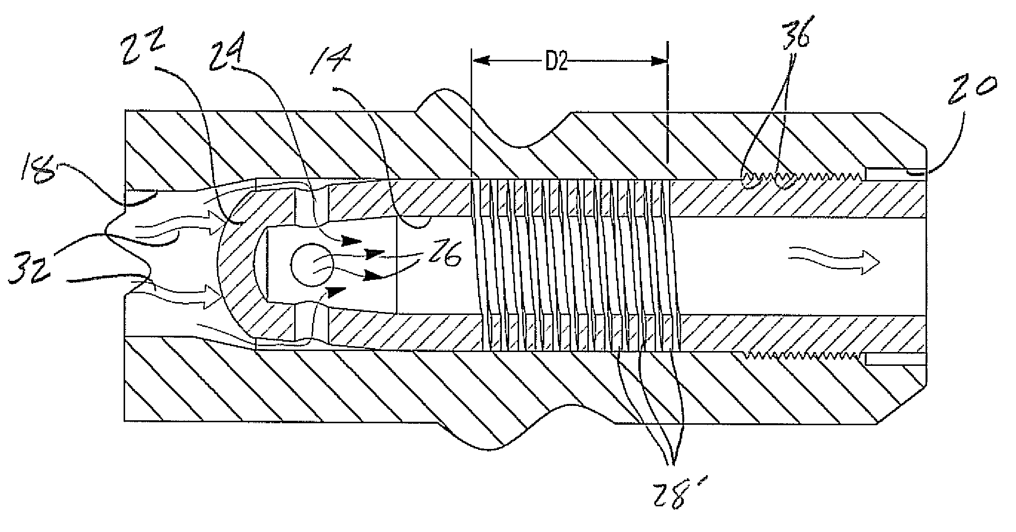
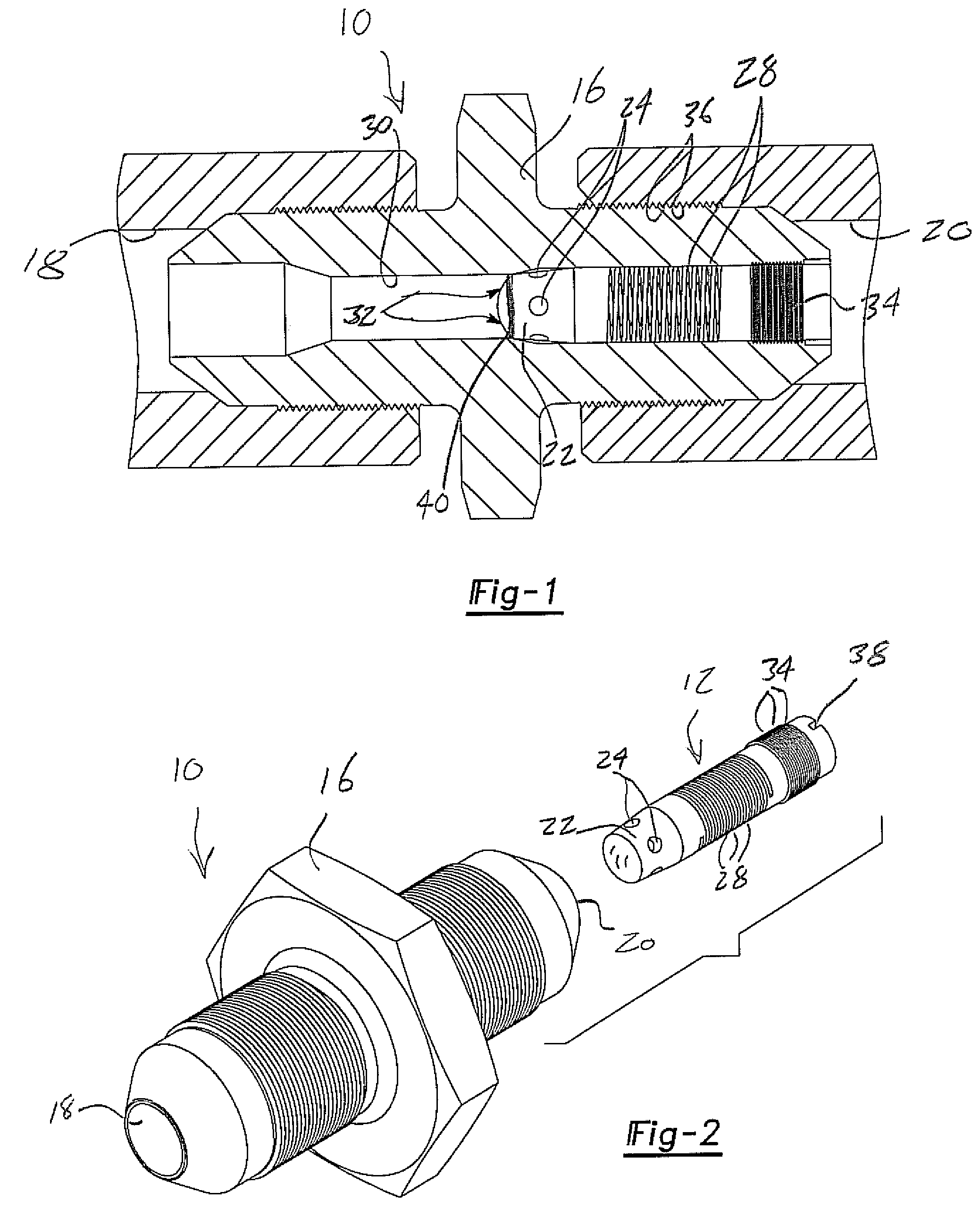
[0021]Referring now to FIG. 1, a cutaway plan view illustration is shown at 10 of a check valve assembly incorporating the one-piece spring and poppet according to a first preferred embodiment of the present inventions. As previously described, the present invention discloses a one-piece and integrally constructed seating portion, this including a poppet and spring, which is an improvement over prior art assemblies in terms of useful life and durability.

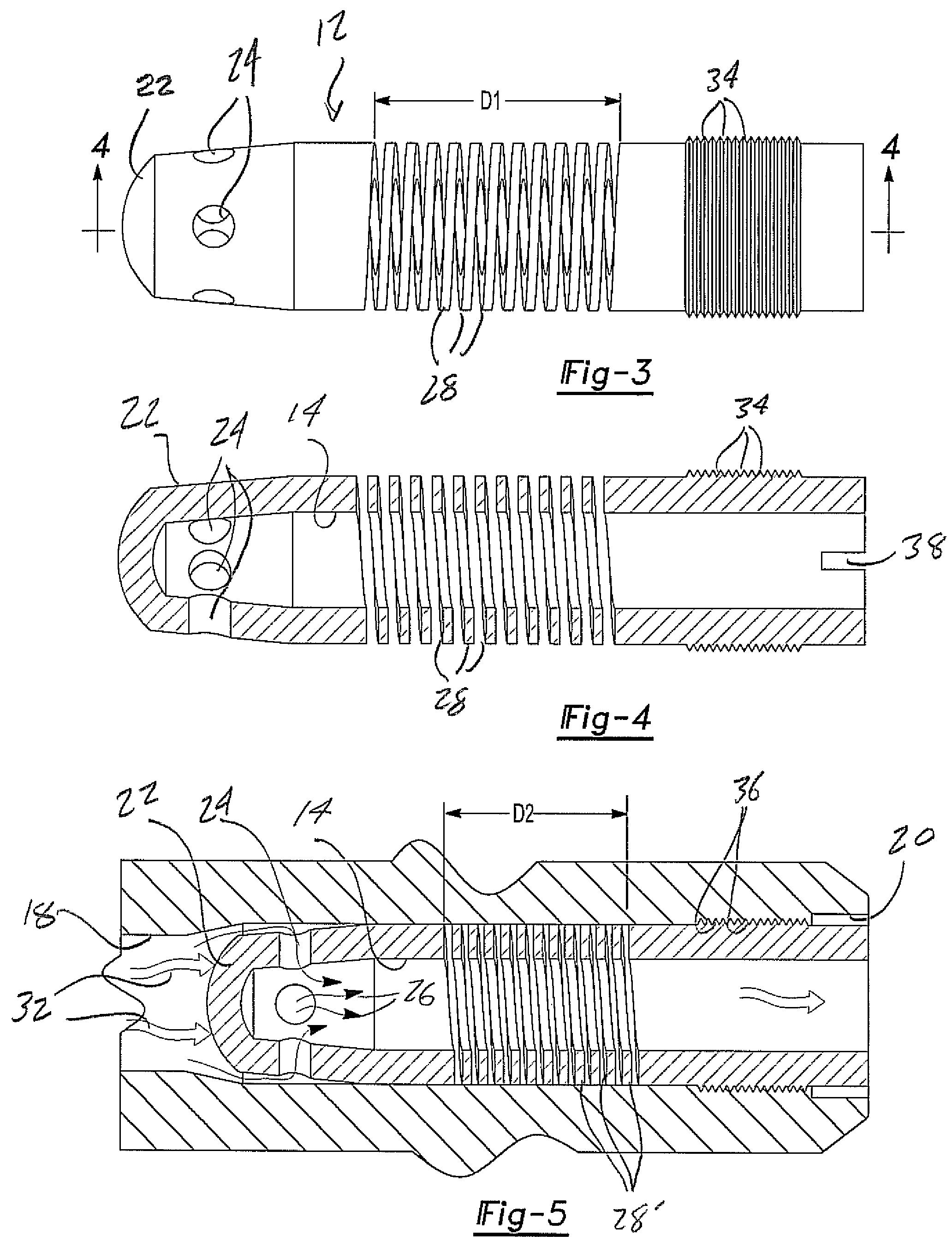
[0022]Referring again to FIG. 1, as well as successively to each of FIGS. 2-5, the one-piece assembly is provided as a three dimensional shaped body, typically rounded and elongated as generally referenced at 12 in FIG. 2, and which is constructed of a resilient material, such as for example a stainless spring steel or a durable plastic. An advantage of the present invention is the ability to produce the combined and integrally formed body 12 of a single material, this again reducing the part count of the spring biased valve seat / pop...


PUM


Abstract

A combined spring and poppet assembly incorporated into a valve housing which communicates with a fluid inlet and outlet. The integral assembly includes an elongated and three dimensional shaped, resilient body positioned in linearly displaceable fashion within the valve housing, and along a path established between the fluid inlet and outlet. The body includes a forward-most disposed poppet which seats against the fluid inlet in a normally flow disrupting fashion. The body further includes an integrally formed spring biasing portion. Upon a pressure in the fluid inlet exceeding a predetermined value, the poppet being caused to unseat from the inlet and to displace linearly against the spring portion, concurrent with fluid flow being established across the outlet.

Description

BACKGROUND OF THE INVENTION[0001]1. Field of the Invention[0002]The present invention relates generally to valve seat assemblies for various not limited to such as check valve and pressure relief applications. More specifically, the present invention discloses a novel and unique one-piece combined spring and poppet, such as which is produced by a helically turned piece of material, the one-piece design providing improved performance and reduced incidence of breakage as compared to prior art and multi-piece spring and poppet assemblies.[0003]2. Description of the Prior Art[0004]The prior art is well documented with various types of valve configurations, including most notably those incorporated into check and pressure relief valve assemblies. A first example of a valve assembly incorporating a plasticized poppet is disclosed in Scholle et al., U.S. Pat. No. 5,255,713, and which includes a central disc part and tapered flange for engaging a valve seat. A plurality of three integrally ...

Claims


Application Information

Patent Timeline
Patent Type & Authority Patents(United States)
IPC IPC(8): F16K15/00
CPCF16K15/026Y10T137/7929Y10T137/7936
Inventor HEDDING, PAUL
Owner HEDDING PAUL
Learn More