Crane assisted pipe lay

a technology of cranes and pipes, applied in the direction of pipe laying and repair, pipe/joints/fittings, pipe-laying vessels, etc., can solve the problems of large dimensions of j-lay towers and typically require a considerable amount of deck spa

Inactive Publication Date: 2010-05-25
HEEREMA MARINE CONTRACTORS NEDERLAND SE
View PDF15 Cites 0 Cited by
  • Summary
  • Abstract
  • Description
  • Claims
  • Application Information

AI Technical Summary

Benefits of technology

[0019]In an embodiment the crane may be used for abandonment and recovery of the pipeline. In the case it is desired to abandon the pipeline, for instance due to the weather conditions, the pipeline may be abandoned by using the crane. This may in particular be advantageous in the present invention as the crane may hold the pipeline during a considerable part of the pipe-laying procedure. When the crane already holds the pipeline, the abandonment can be carried out in an efficient way. When the pipe-laying can be continued, for instance when the weather conditions have improved, the pipeline can be recovered by the crane.
[0020]In an embodiment the crane may be used to transfer the completed pipeline from the pipe-laying vessel to its final hang off location on a production and / or storage facility. This may be advantageous in the present invention as the crane may already be connected to the pipeline during completion of pipe-laying activities.

Problems solved by technology

This installation, in the J-lay method typically a J-lay tower has large dimensions and typically requires a considerable amount of deck space.

Method used


Image

  • Crane assisted pipe lay
  • Crane assisted pipe lay
  • Crane assisted pipe lay

Examples


Embodiment Construction

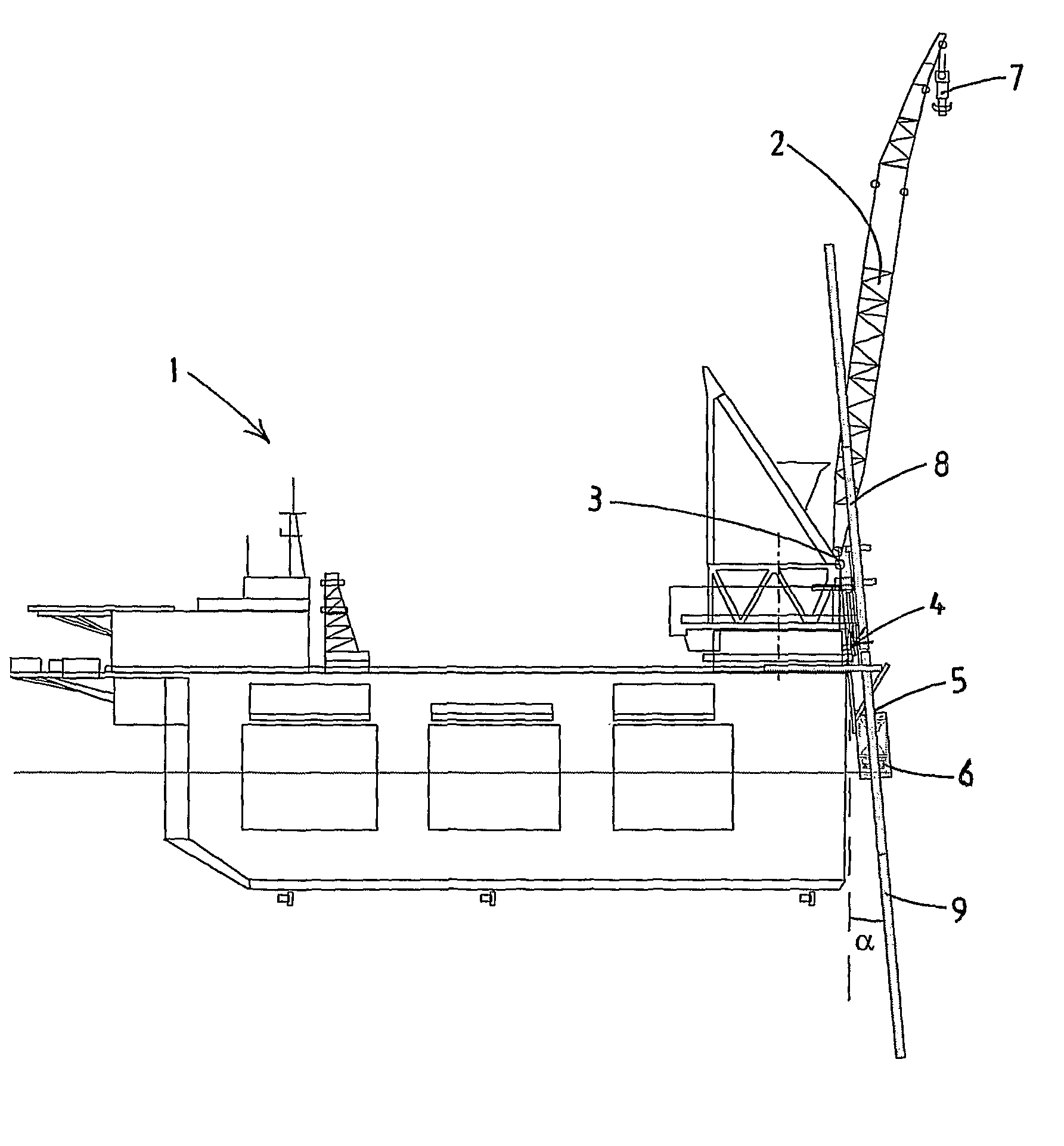
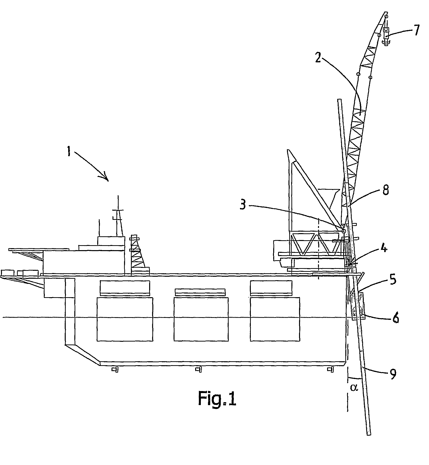
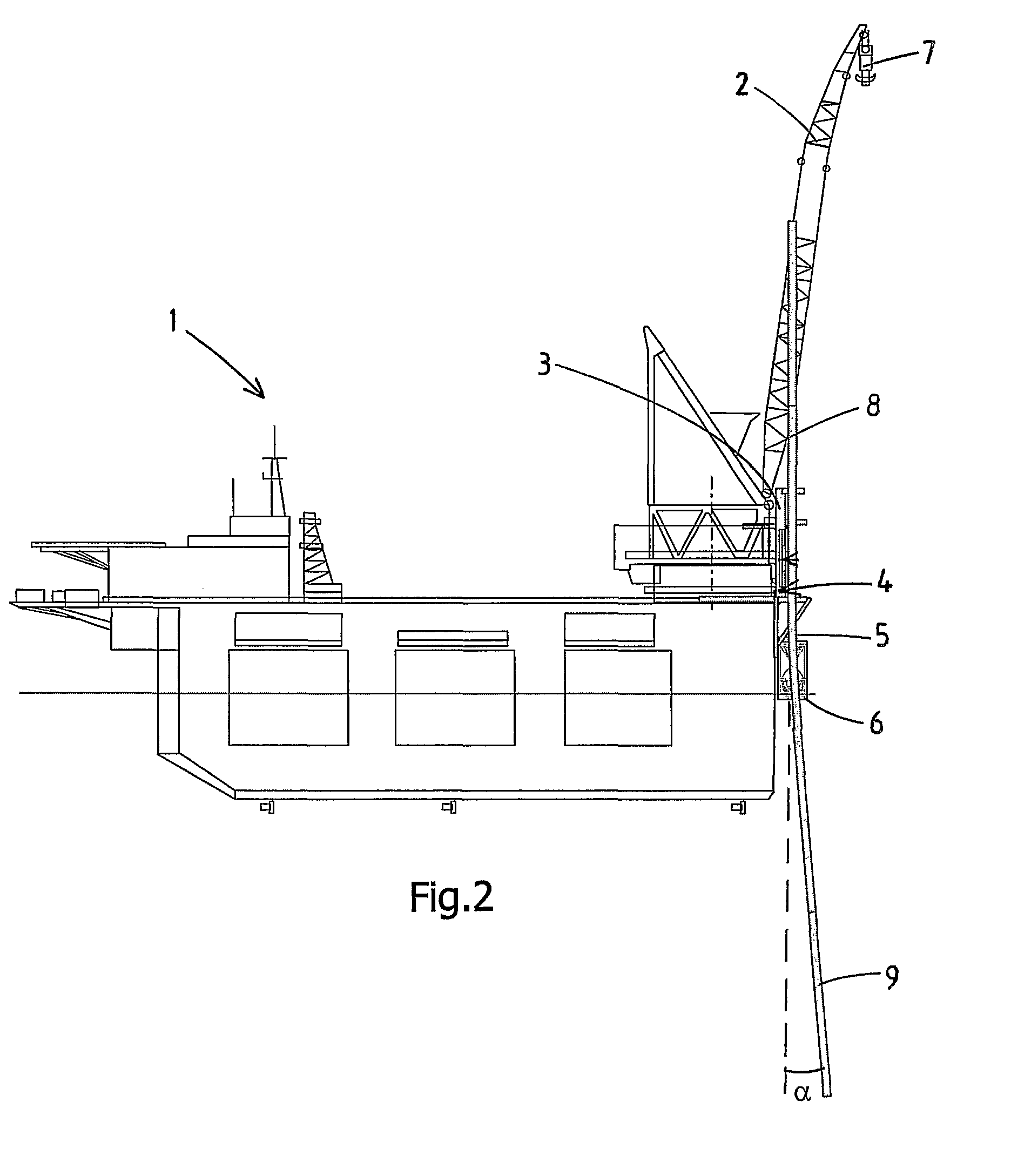
[0042]FIG. 1 shows a pipe-laying vessel 1 according to the invention. The vessel 1 is configured for laying pipes at the bottom of the sea. The vessel 1 comprises a crane 2, a pipeline installation frame 3, a welding station 4, and a hang-off clamp 5.

[0043]The crane 2 is configured to lift pipe sections to be joined in the pipeline from for example a storage location on the deck in a substantially vertical position to the pipeline installation frame to position a bottom end of the pipe section in the vicinity of the upper end of the existing pipeline. The existing pipeline forms a catenary to the bottom of the sea and comprises a number of pipe sections previously joined to each other. The existing pipeline 9 may be held by the hang-off clamp 5.

[0044]The pipeline installation frame 3 is provided to guide and stabilize the pipe section 8. The pipeline installation frame 3 may carry the welding station 4 and the hang-off clamp 5. The pipeline installation frame 3 may also carry furthe...


PUM


Abstract

The present invention relates to a method for laying a pipeline using a vessel (1) comprising a crane (2) comprising the following steps lifting a new pipe section (8) using the crane, placing a new pipe section on an existing pipeline (9), lining up the new pipe section with respect to the existing pipeline, welding the new section to the existing section, lowering the joined new section and the existing pipe, supporting the joined new section so that the crane is free to lift another new section. The invention further relates to a pipe-laying vessel for carrying out such method.

Description

CROSS-REFERENCE TO RELATED APPLICATIONS[0001]This application is the National Stage of International Application No. PCT / NL2007 / 000037, filed Feb. 8, 2007, which claims the benefit of U.S. Provisional Application No. 60 / 771,464, filed Feb. 9, 2006, the contents of which is incorporated by reference herein.FIELD OF THE INVENTION[0002]The present invention relates to a method for laying a pipeline using a vessel and a crane. The invention further relates to a pipe-laying vessel.BACKGROUND OF THE INVENTION[0003]In the offshore industry there is a need for underwater pipelines. These underwater pipelines may be provided by joining pipe sections together in a substantially vertical position to form a pipeline which is lowered from a vessel to an underwater bottom, for instance the bottom of the sea. In such pipe-laying method, which is commonly referred to as a J-lay method a plurality of pipe sections welded to one another, together forming a part of the pipeline, hang down from a vesse...

Claims


Application Information

Patent Timeline
Patent Type & Authority Patents(United States)
IPC IPC(8): F16L1/12
CPCF16L1/207B63B35/03F16L1/19F16L1/12
Inventor HOVINGA, ROBERT PAULVAN ZANDWIJK, CORNELISWASSENAAR, WALTER PETRUS JOHANNESBENARD, CORNELIS
Owner HEEREMA MARINE CONTRACTORS NEDERLAND SE
Why Eureka
Try Eureka