Hole liners for repair of vane counterbore holes

a technology of counterbore holes and hole liners, which is applied in the direction of machines/engines, liquid fuel engines, mechanical equipment, etc., can solve the problems of affecting the free rotation of the vane trunnions within the counterbore, the wear and weathering of the counterbore, and the high cost of parts

Active Publication Date: 2010-05-25
RTX CORP
View PDF19 Cites 40 Cited by
  • Summary
  • Abstract
  • Description
  • Claims
  • Application Information

AI Technical Summary

Problems solved by technology

However, over the course of an engine lifetime, these counterbores become worn and weathered.
In addition to normal vane-induced wear, operation in wet and / or salt-rich environments induces corrosion or pitting in the counterbores, which interferes with free rotation of the vane trunnions within the counterbores.
This is undesirable because these parts are typically very costly due to the high-grade alloys and precision manufacturing necessary to produce these parts.

Method used


Image

  • Hole liners for repair of vane counterbore holes
  • Hole liners for repair of vane counterbore holes
  • Hole liners for repair of vane counterbore holes

Examples


Embodiment Construction

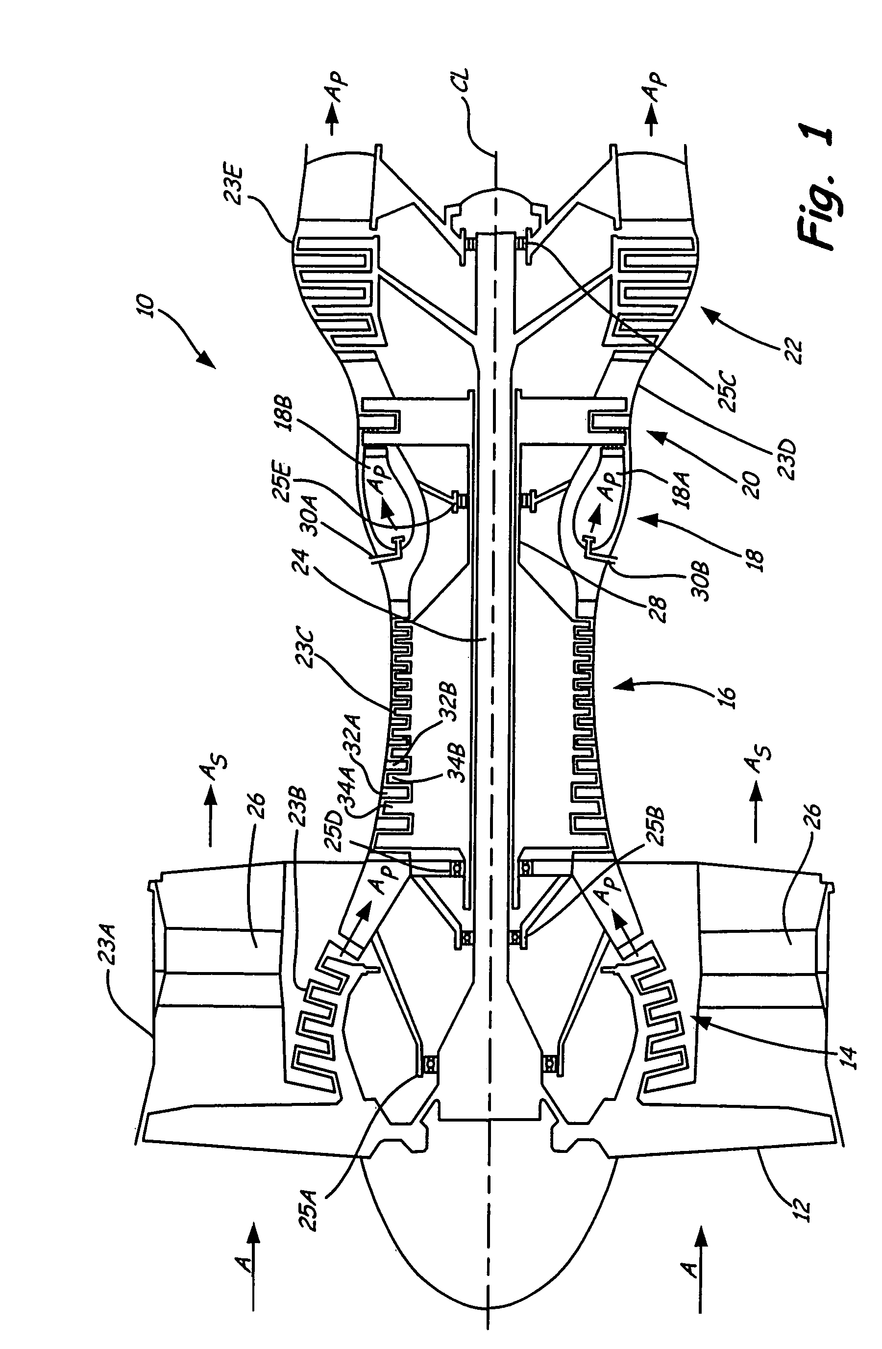
[0014]FIG. 1 shows gas turbine engine 10, in which variable vane hole liners are used. Gas turbine engine 10 comprises a dual-spool turbofan engine having variable stator vanes for which the advantages of the hole liners are particularly well illustrated. Gas turbine engine 10 comprises fan 12, low pressure compressor (LPC) 14, high pressure compressor (HPC) 16, combustor section 18, high pressure turbine (HPT) 20 and low pressure turbine (LPT) 22, which are each concentrically disposed around longitudinal engine centerline CL. Fan 12 is enclosed at its outer diameter within fan case 23A. Likewise, the other engine components are correspondingly enclosed at their outer diameters within various engine casings, including LPC case 23B, HPC case 23C, HPT case 23D and LPT case 23E such that an air flow path is formed around centerline CL.

[0015]Inlet air A enters engine 10 and it is divided into streams of primary air AP and secondary air AS after it passes through fan 12. Fan 12 is rotat...


PUM

PropertyMeasurementUnit
temperaturesaaaaaaaaaa
thicknessaaaaaaaaaa
thicknessaaaaaaaaaa

Abstract

A variable vane shroud for a gas turbine engine comprises a cylindrically shaped body, a hole arranged at a circumference of the body, and a counterbore arranged concentrically around the hole on a radially inward facing surface of the body. The hole is for receiving a trunnion from a variable vane and the counterbore is for receiving a hub from the variable vane. A liner is inserted into the hole and counterbore such that the trunnion and hub are provided with a contact surface. The invention also provides a method for repairing a damaged counterbore in a variable vane shroud. A liner having a shape corresponding to a layer of material removed from the shroud is inserted into the void left by removing damaged material such that the counterbore is restored to pre-damaged dimensions.

Description

BACKGROUND OF THE INVENTION[0001]The present invention is related to gas turbine engines, and in particular to variable vane counterbored holes for engine casings.[0002]Gas turbine engines operate by combusting fuel in compressed air to create heated gases with increased pressure and density. The heated gases are ultimately forced through an exhaust nozzle, which is used to step up the velocity of the exiting gases and in-turn produce thrust for driving an aircraft. In turbofan engines the heated gases are used to drive a turbine for rotating a fan to produce thrust, and to drive a turbine for driving a compressor that provides the compressed air used during combustion. The compressor section of a gas turbine engine typically comprises a series of rotor blade and stator vane stages. At each stage, rotating blades push air past the stationary vanes. Each rotor / stator stage increases the pressure and density of the air. Stators convert the kinetic energy of the air into pressure, and ...

Claims


Application Information

Patent Timeline
Patent Type & Authority Patents(United States)
IPC IPC(8): F01B1/04
CPCB23P6/005F01D17/162F04D29/563F04D29/526F05D2230/80F05D2240/14
Inventor ADDIS, MARK E.
Owner RTX CORP
Why Eureka
Try Eureka