Network addressing scheme for reducing protocol overhead in an optical network

a network address and optical network technology, applied in the field of information networks, can solve the problem of large amount of time consumed, and achieve the effect of reducing time and resources

Inactive Publication Date: 2010-05-25
CISCO SYSTEMS INC
View PDF14 Cites 9 Cited by
  • Summary
  • Abstract
  • Description
  • Claims
  • Application Information

AI Technical Summary

Benefits of technology

[0010]In one embodiment, the present invention reduces the time and resources required to restore a failed circuit (or provision a new circuit) in an optical network by partitioning the nodes of an optical network into zones. The time and resources required are reduced, for example, by localizing the required actions to the zone in which the failure occurred. Localization is effected through the use of a node that acts as a substitute for the source or destination node, as the case may be. This substitute node is referred to herein as a proxy node. The proxy node will normally be a boundary node for the zone in which no failure occurred. If a failure occurs between zones, both boundary nodes can act as proxies for their respective non-boundary nodes, or a full restoration may instead be performed.

Problems solved by technology

However, the restoration of a circuit following a failure in a mesh topology can consume a relatively large amount of time.

Method used


Image

  • Network addressing scheme for reducing protocol overhead in an optical network
  • Network addressing scheme for reducing protocol overhead in an optical network
  • Network addressing scheme for reducing protocol overhead in an optical network

Examples


Embodiment Construction

[0032]The following is intended to provide a detailed description of an example of the invention and should not be taken to be limiting of the invention itself. Rather, any number of variations may fall within the scope of the invention which is defined in the claims following the description.

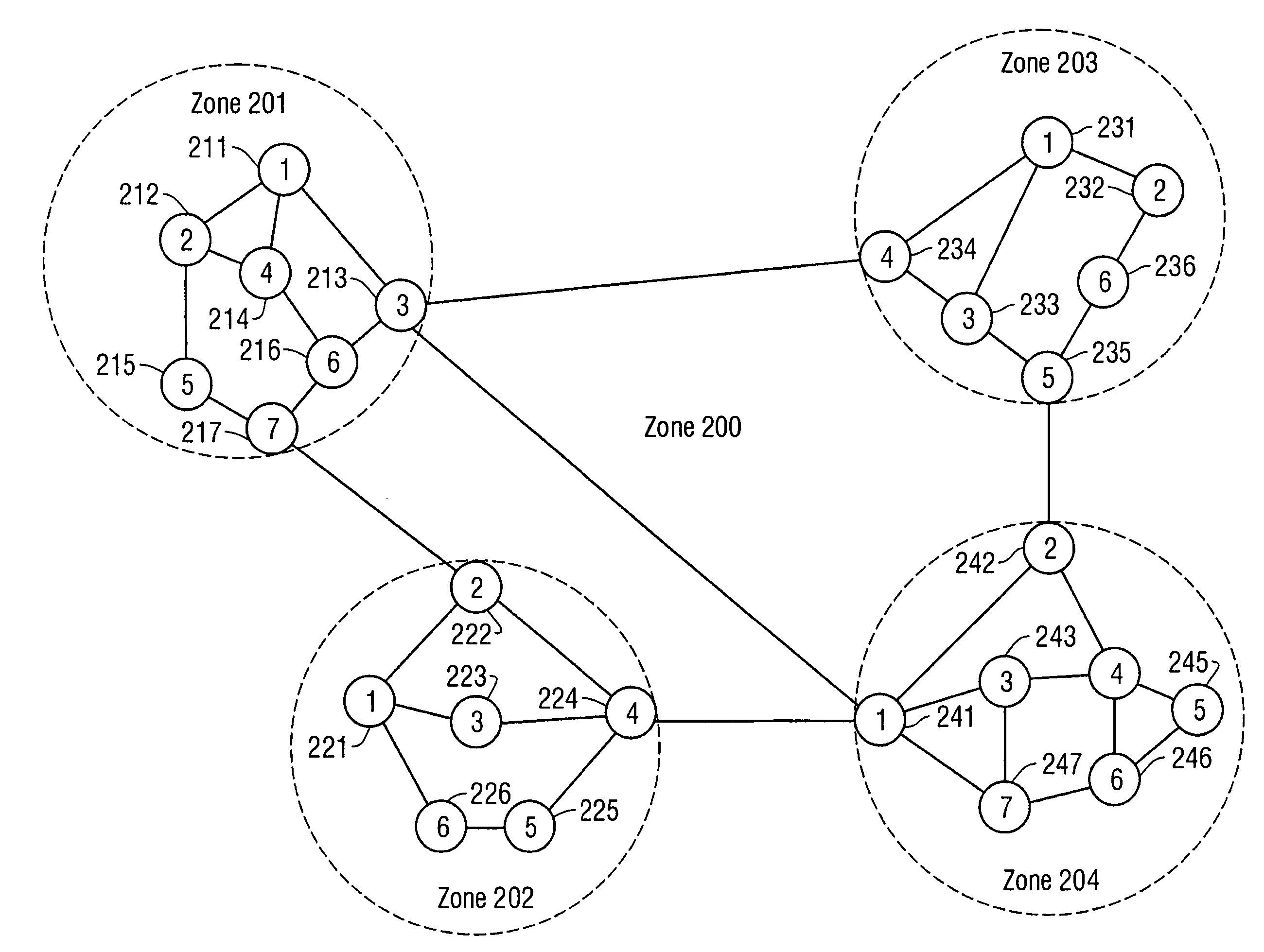
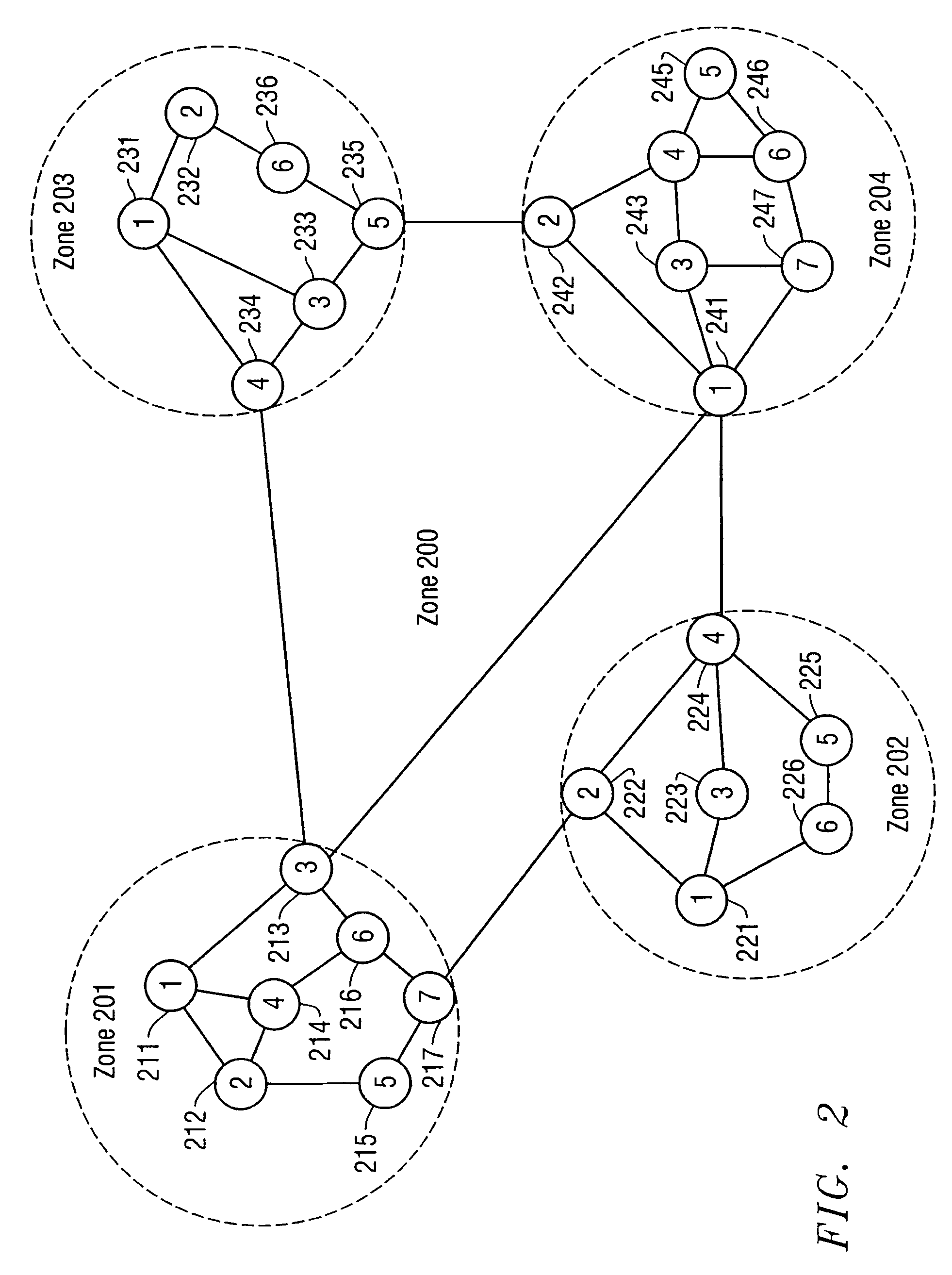
[0033]In one embodiment, a network architecture is described that provides many advantages, including a reduction in protocol overhead experienced by the network, quicker provisioning and restoration of circuits, support for highly efficient protocols, and other advantages. These and other advantages are particularly important when an embodiment of the present invention is used in an optical telecommunications network (e.g., a network employing the Synchronous Optical Network (SONET) protocol, such as that described herein), due in part to the enhancement in restoration times and reduction in protocol overhead provided thereby.

Network Architecture

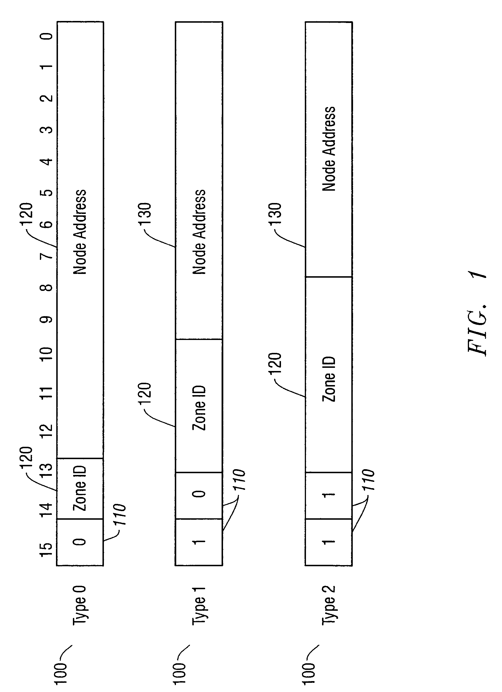
[0034]To limit the size of the topology database...


PUM


Abstract

A method for operating a network and a network architecture implementing the method are described. The method, in one embodiment, begins by grouping a plurality of nodes into zones, where the network includes the plurality of nodes. At least one of the nodes in each one of the zones is one of a plurality of boundary nodes, and each of the boundary nodes in each one of the zones is coupled to a boundary node in another of the zones by one of a first number of inter-zone optical links. One of the zones includes a number of nodes, each of which is coupled to at least one other of the nodes by one of a second number of intra-zone optical links. Next, a non-boundary node is configured to transmit network information to other of the nodes. The non-boundary node is a node in the zone that is not a boundary node. Finally, a boundary node in the zone is configured to limit transmission of the network information through itself to other of the boundary nodes. The network information so limited can be restoration information (in the event of a failure), network topology information, and / or other network information.

Description

CROSS-REFERENCES TO RELATED APPLICATIONS[0001]This application is a continuation-in-part of patent application Ser. No. 09 / 232,397, filed Jan. 15, 1999 and entitled “A METHOD FOR ROUTING INFORMATION OVER A NETWORK,” having A. N. Saleh, H. M. Zadikian, Z. Baghdasarian, and V. Parsi as inventors. This application is assigned to Monterey Networks, Inc., the assignee of the present invention, and is hereby incorporated by reference, in its entirety and for all purposes.[0002]This invention also claims priority from a provisional application entitled “A NETWORK ADDRESSING SCHEME FOR REDUCING PROTOCOL OVERHEAD IN AN OPTICAL NETWORK” (U.S. Provisional Application No. Ser. No. 60 / 137,472), filed Jun. 4, 1999, having S. N. Ali and S. E. Plote as inventors, which is hereby incorporated by reference, in its entirety and for all purposes.[0003]This application is related to patent application Ser. No. 09 / 232,395, filed Jan. 15, 1999 and entitled “A CONFIGURABLE NETWORK ROUTER,” having H. M. Zad...

Claims


Application Information

Patent Timeline
Patent Type & Authority Patents(United States)
IPC IPC(8): H04J1/16H04L12/56
CPCH04L45/02H04L45/28H04L45/04H04L45/03
Inventor SALEH, ALI NAJIBPLOTE, STEVAN E.
Owner CISCO SYSTEMS INC
Why Eureka
Try Eureka