All-optical intensity to DPSK converter

a converter and optical intensity technology, applied in the field of alloptical converters, can solve the problems of inexistent and high price of converters, which combine electronics and optics, and cannot achieve the effect of achieving the effect of reducing the cost of conversion

Active Publication Date: 2010-05-25
FRANCE TELECOM SA
View PDF5 Cites 0 Cited by
  • Summary
  • Abstract
  • Description
  • Claims
  • Application Information

AI Technical Summary

Problems solved by technology

These converters, which combine electronics and optics, are very expensive for frequencies above 20 GHz and are non-existent for frequencies above 40 GHz.
The problem is therefore to produce an all-optical converter for converting an intensity-modulated optical signal into an optical signal modulated to the DPSK format.

Method used


Image

  • All-optical intensity to DPSK converter
  • All-optical intensity to DPSK converter
  • All-optical intensity to DPSK converter

Examples


Embodiment Construction

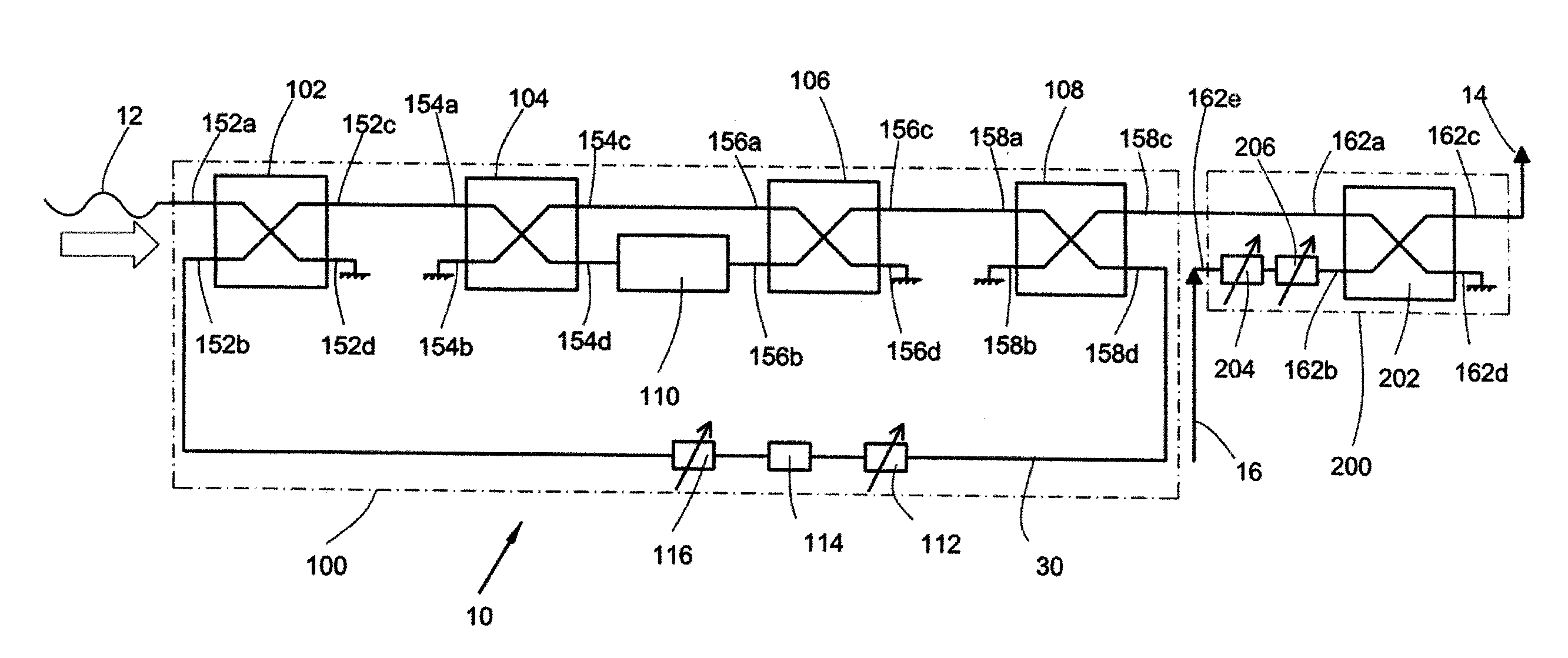
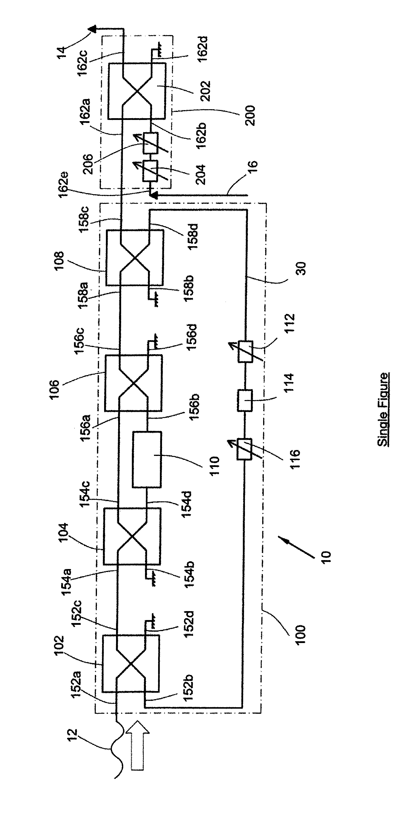
[0033]The single FIGURE depicts an all-optical converter 10 that performs the conversion of an intensity-modulated optical signal into an optical signal modulated to the DPSK format.

[0034]The converter 10 comprises a first input 152a, onto which a first optical signal 12 is injected. The optical signal 12 represents a data sequence and is modulated in intensity according to an OOK format. This optical signal may have been generated from an electrical signal and an optoelectronic modulator that transforms the OOK-modulated electrical signal into an OOK-modulated optical signal.

[0035]The converter 10 comprises a second input 162e, onto which there is injected an optical carrier 16 (continuous or not) that is then modulated to the DPSK format.

[0036]The converter 10 comprises a first output 162c on which an optical signal 14 modulated to the DPSK format is delivered.

[0037]The converter 10 thus carries out the all-optical conversion of an intensity-modulated optical signal into an optica...


PUM


Abstract

An all-optical converter (10) for converting an intensity-modulated optical signal into an optical signal modulated to the DPSK format, includes a first input (152a) for a first intensity-modulated optical signal (12), a differential encoding module (100) adapted to perform a differential encoding between the first signal (12) and a second optical signal synchronous with the first signal (12), a device adapted to modulate (200) the phase of an optical signal (16) according to the differential encoding performed by the differential encoding module (100), and an output (162c) of the device adapted to modulate (200) delivering an optical signal modulated to the DPSK format (14).

Description

CROSS-REFERENCE TO RELATED APPLICATION[0001]The present application is a national stage of and claims priority of International Patent Application Serial No. PCT / FR2003 / 03809, filed Dec. 19, 2003, the content of which is hereby incorporated by reference in its entirety.BACKGROUND OF THE INVENTION[0002]The invention concerns an all-optical converter for converting an intensity-modulated optical signal into an optical signal modulated to the DPSK format. It finds an application in the field of optical transmissions.[0003]Intensity modulation by On / Off Keying or OOK is known. In this case, a pulse represents a “1” and an absence of pulse represents a “0”.[0004]Differential phase shift modulation (Differential Phase Shift Keying or DPSK) is known. In the DPSK format, the information is transported in the phase difference between two adjacent pulses.[0005]Transmission to the DPSK format is advantageous since the sensitivity is better. In addition in optical mode, it is easy to analyse th...

Claims


Application Information

Patent Timeline
Patent Type & Authority Patents(United States)
IPC IPC(8): H04B10/00H04B10/50H04B10/516H04B10/556
CPCH04B10/505H04B10/5055H04B10/5561H04B10/516H04B2210/517
Inventor CUENOT, BENJAMINLE ROUZIC, ESTHERBROCHIER, NICOLAS
Owner FRANCE TELECOM SA
Why Eureka
Try Eureka