Al technical title is built by PatSnap Al team. It summarizes the technical point description of the patent document.
a microfluidic and cytometry technology, applied in the field of microfluidic cytometry systems, can solve the problems of limiting fluid switching cell sorters, unable to meet the requirements of the type of system does not lend itself to sterility and operator protection. protection, and facilitate cytometry analysis of viral particles, the effect of facilitating cytometry analysis
Active Publication Date: 2011-01-13
SONY CORP +1
View PDF61 Cites 73 Cited by
Summary
Abstract
Description
Claims
Application Information
AI Technical Summary
This helps you quickly interpret patents by identifying the three key elements:
Problems solved by technology
Method used
Benefits of technology
[0029]In yet another embodiment, a microfluidic device is disclosed, comprising a substrate, a microfluidic flow channel formed in said substrate, wherein said flow channel extends through a portion of said substrate adapted to facilitate cytometry analysis of cells flowing in said flow channel, and an optical waveguide formed in said flow channel.
[0030]In another embodiment, a microfluidic device is disclosed, comprising a substrate, a microfluidic flow channel formed in said substrate, wherein said flow channel extends through a portion of said substrate adapted to facilitate cytometry analysis of cells flowing in said flow channel, an optical waveguide formed in said flow channel, and a reflective surface disposed within said flow channel.
[0031]In yet another embodiment, a method of determining a pharmacological efficacy is disclosed, the method comprising the steps of: a) providing a microfluidic device, said microfluidic device comprising a substrate, a microfluidic flow channel formed in said substrate, wherein said flow channel extends through
Problems solved by technology
Droplet cell sorters, however, are not particularly biosafe.
Unfortunately, this type of system does not lend itself to the sterility and operator protection required for rou
Method used
Image
Click on the blue label to locate the original text in one second.
Reading with bidirectional positioning of images and text.
Examples
Embodiment Construction
[0059]For the purposes of promoting an understanding of the principles of the disclosure, reference will now be made to the embodiments illustrated in the drawings and specific language will be used to describe the same. It will nevertheless be understood that no limitation of the scope of the disclosure is thereby intended, such alterations and further modifications in the illustrated device, and such further applications of the principles of the disclosure as illustrated therein are contemplated as would normally occur to one skilled in the art to which the disclosure relates.
Microfluidic Device Having Light Collection from Multiple Directions
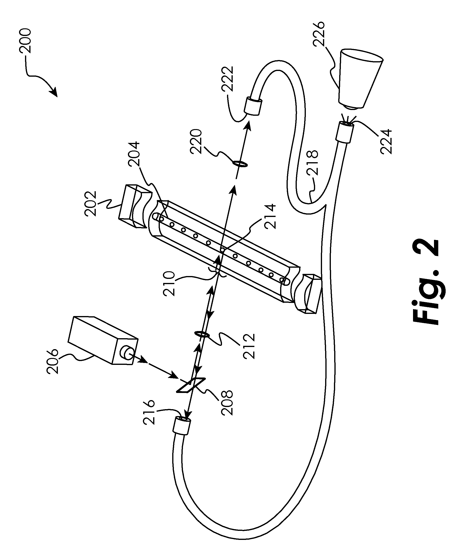
[0060]Certain embodiments of the present disclosure are generally directed to systems for the analysis of a sample on a microfluidic device, using cytometry (such as flow cytometry or image cytometry). In order to detect or identify cells during cytometry operations, a source (such as a laser) of electromagnetic radiation (such as visible lig...
PUM
Abstract
The present disclosure relates to microfluidic devices adapted for facilitating cytometry analysis of particles flowing therethrough. In certain embodiments, the microfluidic devices allow light collection from multiple directions. In certain other embodiments, the microfluidic devices use spatial intensity modulation. In certain other embodiments, the microfluidic devices have magnetic field separators. In certain other embodiments, the microfluidic devices have the ability to stack. In certain other embodiments, the microfluidic devices have 3-D hydrodynamic focusing to align sperm cells. In certain other embodiments, the microfluidic devices have acoustic energy couplers. In certain other embodiments, the microfluidic devices have phase variation producing lenses. In certain other embodiments, the microfluidic devices have transmissive and reflective lenses. In certain other embodiments, the microfluidic devices have integrally-formed optics. In certain other embodiments, the microfluidic devices have non-integral geographically selective reagent delivery structures. In certain other embodiments, the microfluidic devices have optical waveguides incorporated into their flow channels. In certain other embodiments, the microfluidic devices have optical waveguides with reflective surfaces incorporated into their flow channels. In certain other embodiments, the microfluidic devices have virus detecting and sorting capabilities. In certain other embodiments, the microfluidic devices display a color change to indicate use or a result.
Description
CROSS-REFERENCE TO RELATED APPLICATIONS[0001]The present application claims the benefit of the following: U.S. Provisional Patent Application No. 61 / 224,533, which was filed Jul. 10, 2009, U.S. Provisional Patent Application No. 61 / 223,417, which was filed Jul. 7, 2009, U.S. Provisional Patent Application No. 61 / 223,408, which was filed Jul. 7, 2009, U.S. Provisional Patent Application No. 61 / 223,732, which was filed Jul. 8, 2009, U.S. Provisional Patent Application No. 61 / 223,735, which was filed Jul. 8, 2009, U.S. Provisional Patent Application No. 61 / 223,736, which was filed Jul. 8, 2009, U.S. Provisional Patent Application No. 61 / 223,737, which was filed Jul. 8, 2009, U.S. Provisional Patent Application No. 61 / 223,416, which was filed Jul. 7, 2009, U.S. Provisional Patent Application No. 61 / 223,419, which was filed Jul. 7, 2009, U.S. Provisional Patent Application No. 61 / 224,528, which was filed Jul. 10, 2009, U.S. Provisional Patent Application No. 61 / 223,420, which was filed J...
Claims
Application Information
Patent Timeline
Application Date:The date an application was filed.
Publication Date:The date a patent or application was officially published.
First Publication Date:The earliest publication date of a patent with the same application number.
Issue Date:Publication date of the patent grant document.
PCT Entry Date:The Entry date of PCT National Phase.
Estimated Expiry Date:The statutory expiry date of a patent right according to the Patent Law, and it is the longest term of protection that the patent right can achieve without the termination of the patent right due to other reasons(Term extension factor has been taken into account ).
Invalid Date:Actual expiry date is based on effective date or publication date of legal transaction data of invalid patent.