Charging in a communication system

Inactive Publication Date: 2010-05-25
NOKIA CORP
View PDF50 Cites 5 Cited by
  • Summary
  • Abstract
  • Description
  • Claims
  • Application Information

AI Technical Summary

Benefits of technology

[0016]Preferably a charging unit of the system compares the said estimate with a pre-paid balance of an account of the user who initiated the connection and if the balance is insuffi

Problems solved by technology

However, in order to successfully implement a pre-paid system the operator's network mus

Method used


Image

  • Charging in a communication system
  • Charging in a communication system
  • Charging in a communication system

Examples


Embodiment Construction

[0021]The present invention will be described by way of example with reference to the architecture of a 3G network. However, it will be understood that it can be applied to any other suitable form of network.

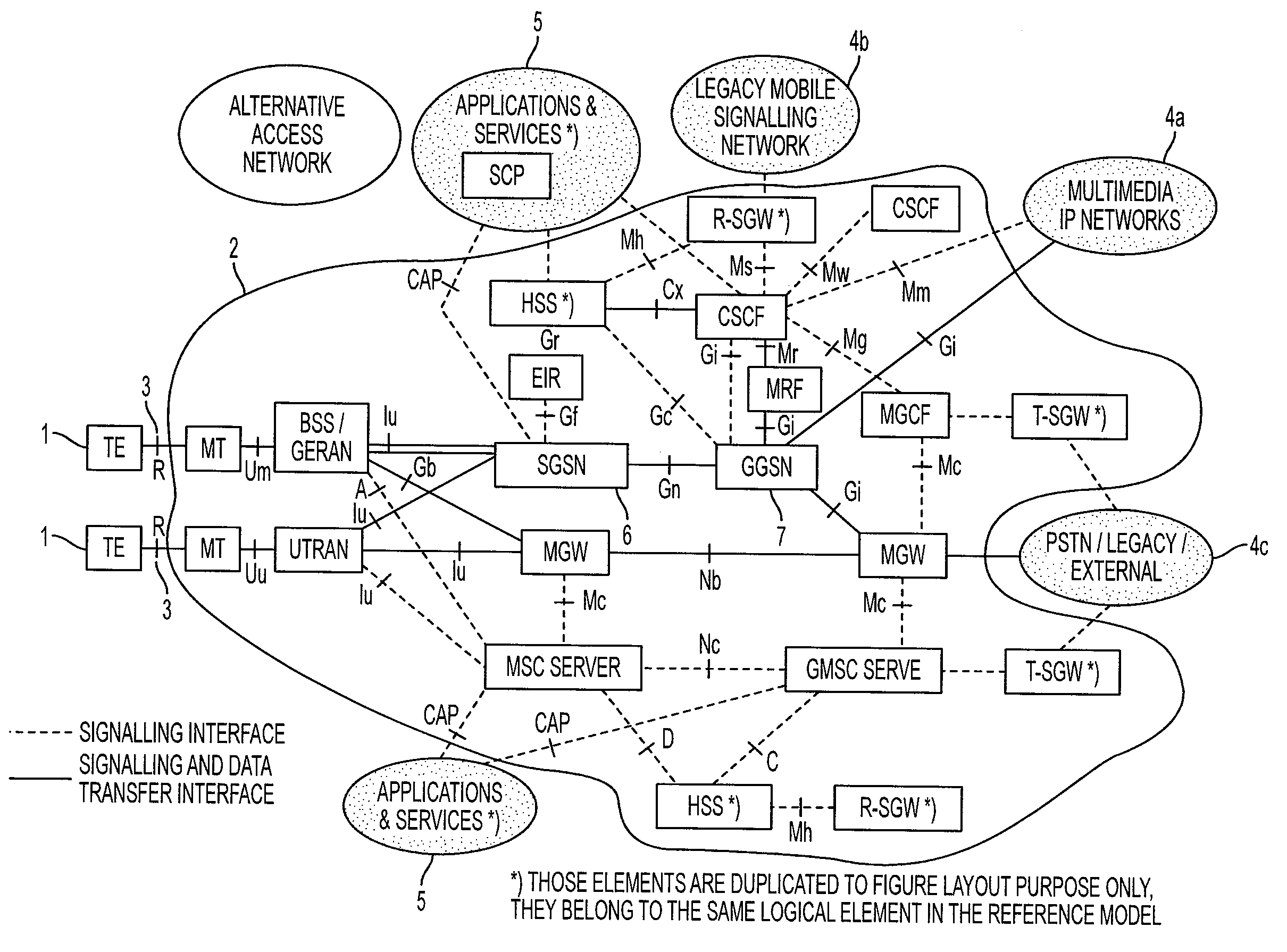
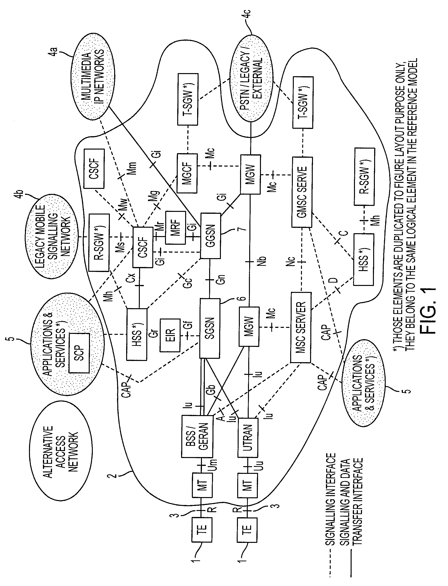
[0022]FIG. 1 depicts the architecture of an all-IP (internet protocol) UMTS communication system. Boxes and ellipses in FIG. 1 indicate network elements, which are annotated by their standard abbreviations. The network elements are connected by interfaces indicated by lines, whose types are indicated by their standard abbreviations next to the lines. Network elements whose abbreviations carry the suffix “*)” in FIG. 1 are duplicated in the figure for ease of layout, but belong to the same logical element in the UMTS reference model.

[0023]In the system of FIG. 1, items of terminal equipment (TE) 1 can communicate with the UMTS network 2 via radio (R) interface 3. By this means the TEs can communicate with other TEs that are connected directly to the UMTS network or are connected ...


PUM


Abstract

A method and system for charging for services in a communication system comprises a charging entity and at least two connection support entities for providing resources to support a connection in the communication system. Various steps include detecting initiation of a connection by the connection support entities; generating a charging identity for identifying the connection; determining a first charge for supporting the connection by the first connection support entity; determining a second charge for the support of the connection by the second connection support entity; transmitting a first charging message from the first connection support entity to the charging entity, the message specifying the first charge and including the charging identity; and transmitting a second charging message from the second connection support entity to the charging entity, the second charging message specifying the second charge and including the charging identity.

Description

REFERENCE TO RELATED APPLICATIONS[0001]This application is a Continuation of U.S. Ser. No. 10 / 450,609, filed on Nov. 24, 2003, which is a national stage of PCT / IB01 / 02815, filed on Dec. 30, 2001. The subject matter of these earlier filed applications is hereby incorporated by reference.BACKGROUND OF THE INVENTION[0002]This invention relates to charging for services in a communication system such as a mobile telephony system.[0003]In a basic communication system a simple communication network is provided, which can link together two communication terminals so that the terminals can communicate with each other in a communication session or call. Conventionally, a designated entity in the network uses a stored tariff to determine a charge for a call based on the call's duration. Each terminal user has a charging account with the operator of the network. The charge for a call is then allocated to the charging account of the user of the terminal that originated the call. When a call is i...

Claims


Application Information

Patent Timeline
IPC IPC(8): H04M11/00H04M15/00G06Q50/00G06Q30/00H04M17/00H04W4/24
CPCH04M15/31H04W4/24H04M15/49H04M15/55H04M15/854H04M17/00H04M17/10H04M17/106H04M15/41H04M2017/14H04M2215/0164H04M2215/2026H04M2215/204H04M2215/32H04M2215/44H04M2215/46H04M2215/8166H04M2215/96H04M15/00
Inventor KOSKINEN, JUHA-PEKKAVALLINEN, JUHAHOPEAHARJU, MERJA
Owner NOKIA CORP
Why Eureka
Try Eureka