
Continuous firing type trigger structure for toy gun

a toy gun and trigger technology, applied in the field of toy guns, can solve the problems of increasing manufacturing costs and less attractive single-fired toy guns for most peopl

Inactive Publication Date: 2010-06-01
WEI WILSON
View PDF11 Cites 18 Cited by
  • Summary
  • Abstract
  • Description
  • Claims
  • Application Information

AI Technical Summary

Benefits of technology

"The present invention provides a continuous firing type trigger structure for toy guns, which eliminates the drawbacks of prior art designs. The mechanism includes a valve body, an enclosed socket, a piston, a hammer, and a sliding shell. The valve body is connected to the enclosed socket and has an axial through hole with a gas outlet valve tube inserted through it. The gas outlet valve tube has an air inlet and an air passage and is supported by a spring. The piston is affixed to the sliding shell and inserted into the enclosed socket. The hammer is pivoted to the toy gun and has a retaining flange releasably engaged by a spring-supported sear. The mechanism allows for continuous firing of airsoft bullets from the toy gun."

Problems solved by technology

This single firing mode toy gun is less attractive to most people.
However, because these continuous firing mode trigger structures are commonly formed of a big number of parts, their fabrication requires much time and labor, increasing the manufacturing cost.
Further, the common back sliding action of the gun barrel to cause a bullet firing action according to the continuous firing mode trigger structures does not simulate the firing operation of a real gun.

Method used


Image

  • Continuous firing type trigger structure for toy gun
  • Continuous firing type trigger structure for toy gun
  • Continuous firing type trigger structure for toy gun

Examples


Embodiment Construction

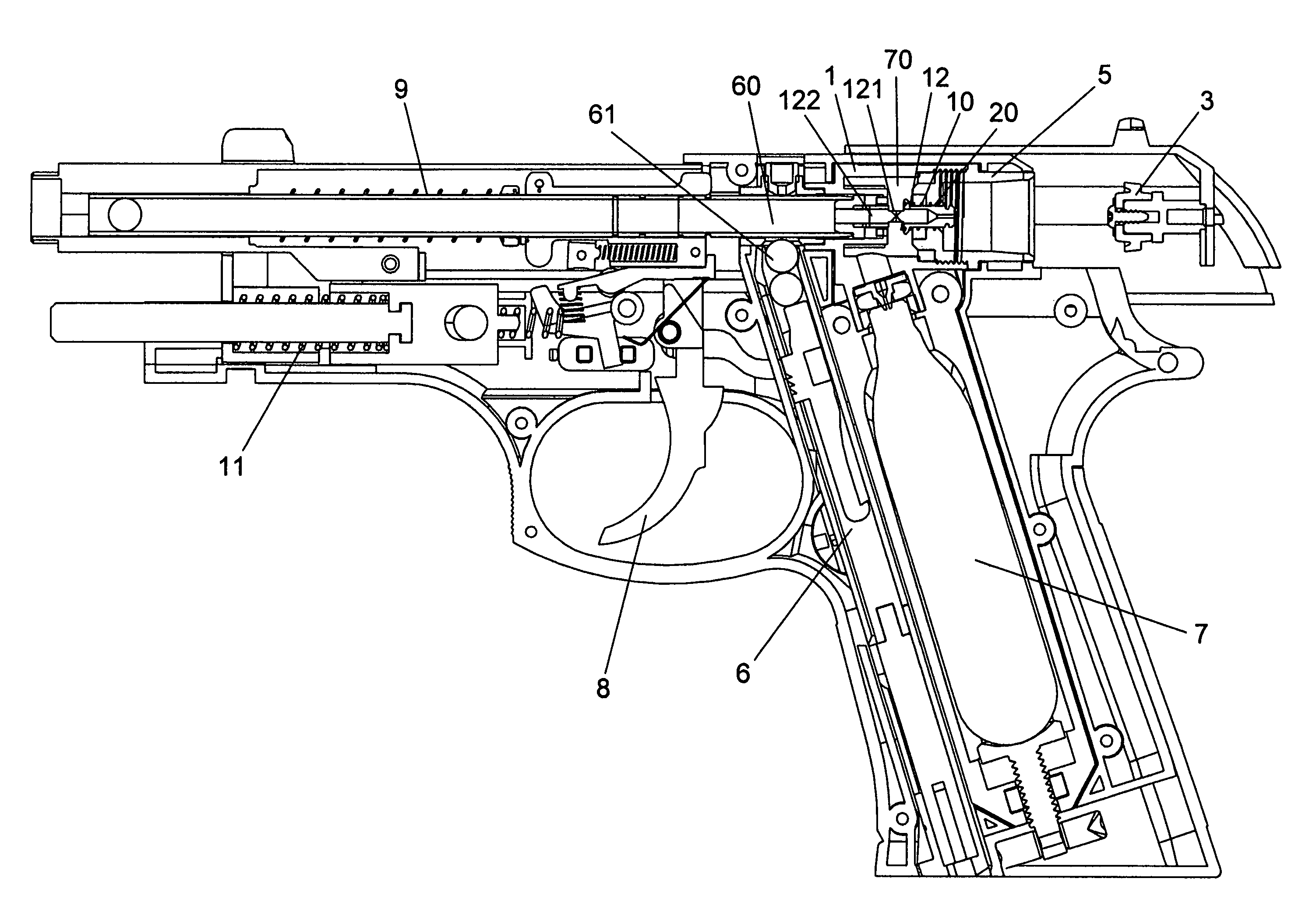
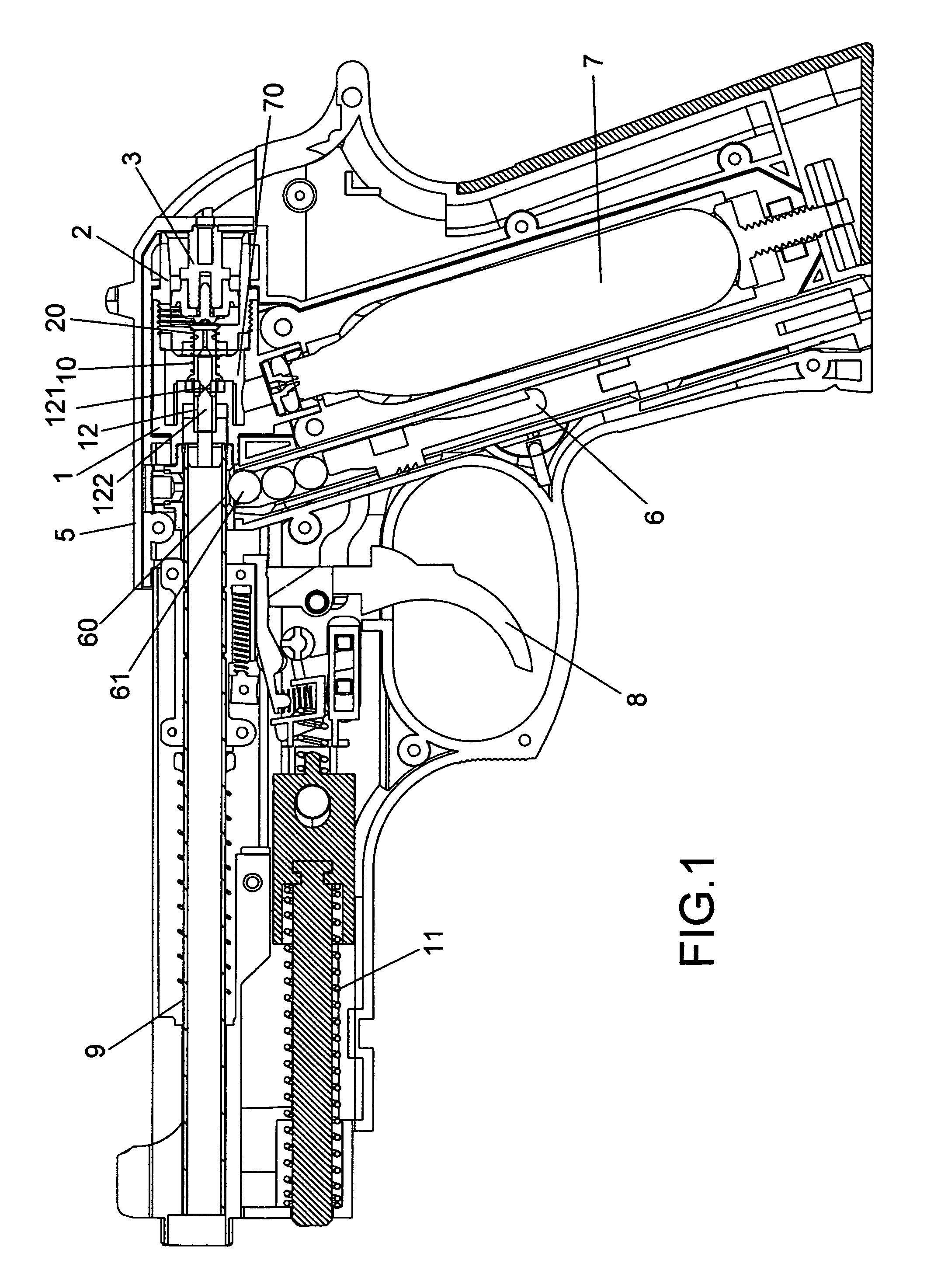
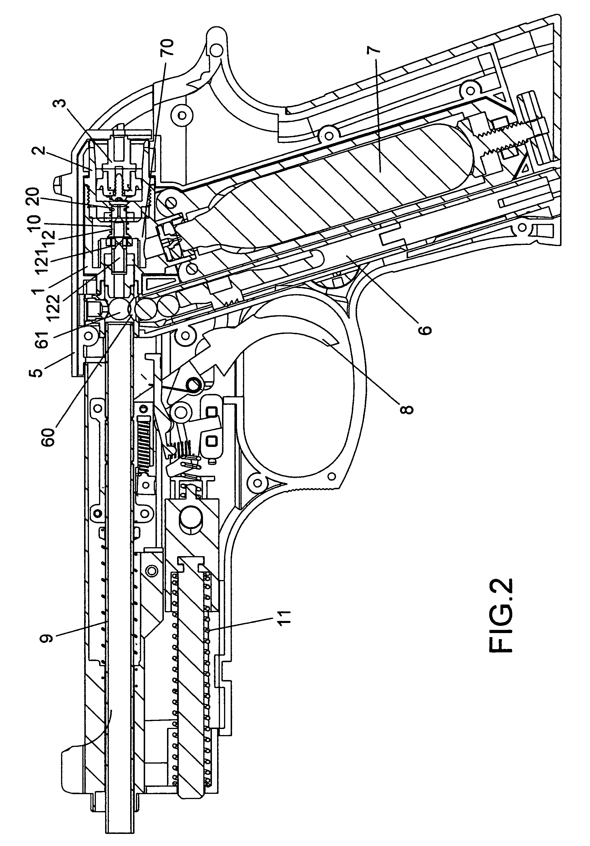
[0017]Referring to the annexed drawings in detail, a continuous firing type trigger structure in accordance with the present invention is shown used in a toy gun (air soft gun / BB-gun), comprising a valve body 1, an enclosed socket 2, a piston 3, a hammer 4, and a sliding shell 5. The valve body 1 is disposed behind the output port 60 of a magazine clip (bullet feeder) 6 in air communication with the air outlet nozzle 70 of a high-pressure gas can 7. The enclosed socket 2 is axially connected to the rear end of the valve body 1. A gas outlet valve tube 12 is inserted through an axial through hole 20 that extends through the front and rear sides of the valve body 1, and supported on a spring 10. The gas outlet valve tube 12 has an air passage 122 and an air inlet 121 at one end of the air passage 122. The spring 10 imparts a pressure to the gas outlet valve tube 12, holding the gas outlet valve tube 12 in a position where the air inlet 121 is isolated from the inside space of the valv...


PUM


Abstract

A continuous firing type trigger structure of a toy gun (air soft gun / BB-gun) includes a valve body disposed behind the output port of a magazine clip in air communication with the gas outlet of a high-pressure gas can, an enclosed socket connected to the rear side of the valve body, a valve tube inserted through the valve body, a spring that pushes the valve tube forwards to keep the air inlet of the valve tube not in communication with the inside space of the valve body, and a piston inserted into the enclosed socket and fixedly connected to a sliding shell on the outside of the toy gun such that the valve tube is moved with the piston forwards (or backwards) to let a high pressure gas be discharged out of the high-pressure gas can into the valve tube to drive an airsoft gun out of the toy gun and to force the piston and the sliding shell backwards after triggering of the trigger of the toy gun, for enabling the piston and the sliding shell to be immediately returned by a return spring for a next firing operation. A hammer is pivoted to the toy gun and releasably secured in place by a spring-supported sear for firing one single airsoft bullet per each hammering action.

Description

BACKGROUND OF THE INVENTION[0001]1. Field of the Invention[0002]The present invention relates to a toy gun (air soft gun / BB-gun) and more particularly, to a continuous firing type trigger structure for toy gun (air soft gun / BB-gun).[0003]2. Description of the Related Art[0004]An air soft gun / BB-gun is a tool for training of shooting techniques or playing of a shooting game. An air soft gun / BB-gun utilizes a high pressure gas to drive airsoft bullets out of the gun barrel, i.e., an air soft gun / BB-gun comprises an accommodation chamber accommodating a high-pressure gas can and a valve tube for guiding out discharged high pressure gas from the high-pressure gas can to drive an airsoft bullet out of the gun barrel. However, the user must pull the firing mechanism to the initial position manually after firing of one airsoft bullet so that the air soft gun / BB-gun can be operated to fire another airsoft bullet again. This single firing mode toy gun is less attractive to most people. There...

Claims


Application Information

Patent Timeline
Patent Type & Authority Patents(United States)
IPC IPC(8): F41B11/00F41B11/62
CPCF41B11/723
Inventor WEI, WILSON
Owner WEI WILSON
Learn More