Connector having a plug, a socket, and a tubular shield member with an elastic arm

a technology of connectors and shields, applied in the direction of coupling device connections, electrical equipment, coupling protective earth/shielding arrangements, etc., can solve the problems of electrical devices connected to the relevant electric cables, troublesome maintenance, and loose connectors of type, and achieve the effect of increasing the reliability of connection

Active Publication Date: 2010-06-01
ORMON CORP
View PDF29 Cites 47 Cited by
  • Summary
  • Abstract
  • Description
  • Claims
  • Application Information

AI Technical Summary

Benefits of technology

[0007]The present invention has been devised to solve the problems described above, and an object thereof is to provide a connector capable of preventing entering of external signals and preventing malfunctioning of the electrical device.
[0019]According to the present embodiment, the tubular shield member is reliably electrically connected to the shield wire of the electric cable by way of the caulking portion serving as the joint, whereby the connection reliability increases.

Problems solved by technology

Conventionally, a screw-type connector (see Japanese Unexamined Patent Publication No. 2002-237348) for electrically connecting electric cables on the same axis center by way of a screw has been known for a connector, but the screw-type connector may loosen when microscopic vibration and the like is applied, and torque management is always necessary, whereby maintenance becomes troublesome.
However, in both connectors described above, an external signal may enter the electric cable from the connector, and thus an electrical device connected to the relevant electric cable may malfunction.

Method used


Image

  • Connector having a plug, a socket, and a tubular shield member with an elastic arm
  • Connector having a plug, a socket, and a tubular shield member with an elastic arm
  • Connector having a plug, a socket, and a tubular shield member with an elastic arm

Examples


first embodiment

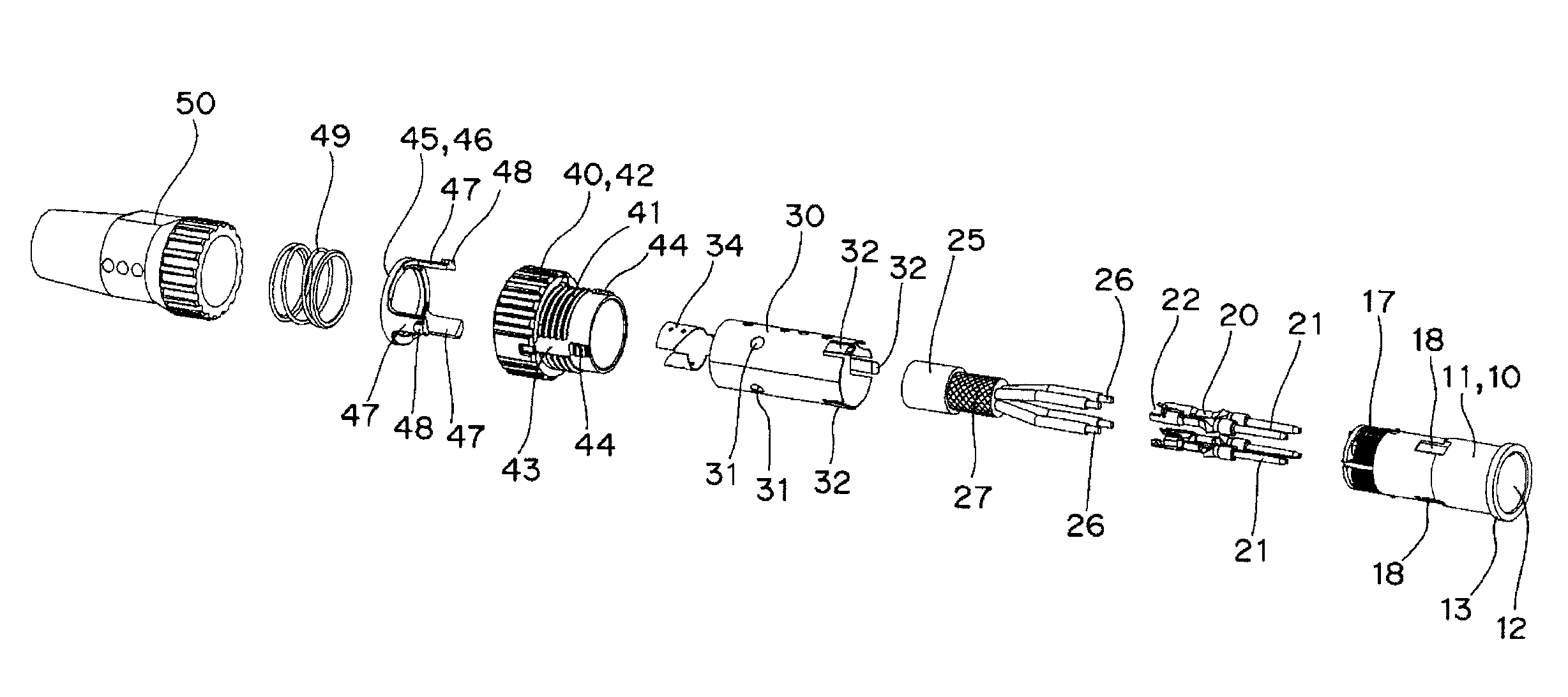
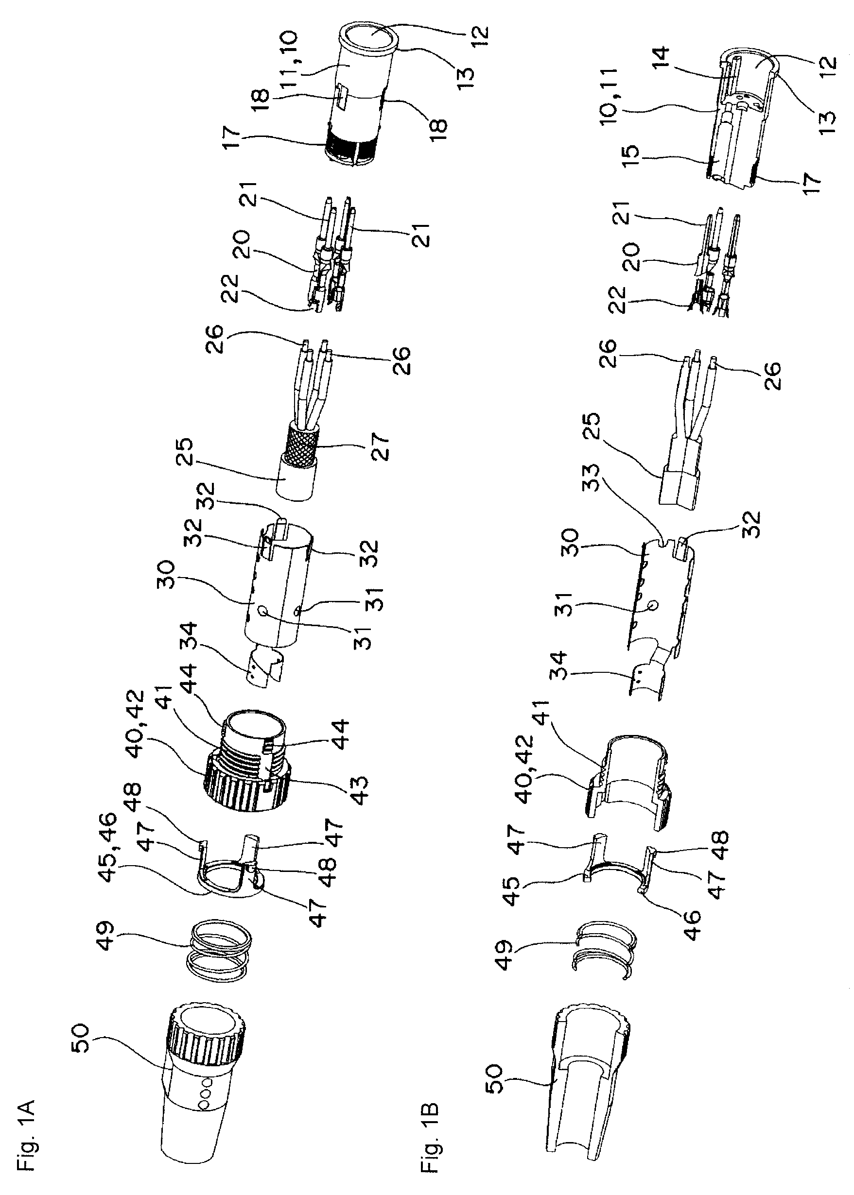
[0049]As shown in FIGS. 1A to 11D, a first embodiment is a case applied to a connector including a bayonet-type plug 10 and a socket 60.

[0050]As shown in FIGS. 1A and 1B, the bayonet-type plug 10 includes a plug main body 11, four pin terminals 20, an electric cable 25, a shield member 30 also functioning as a reinforcement member, a plug holder 40, a slip-out preventing member 45, a coil spring 49, and a plug housing 50.

[0051]The plug main body 11 is a columnar resin molded article, where an annular rib 13 for preventing slip-out of the plug holder 40, to be hereinafter described, is arranged at an opening edge of a fit-in recessed site 12 arranged at one end face side. A guide protrusion 14 is arranged in a projection manner to lie along the axis core direction at the inner peripheral surface of the fit-in recessed site 12. At the other end face side of the plug main body 11, four terminal holes 15 communicating to the fit-in recessed site 12 are formed. Furthermore, a great numbe...

second embodiment

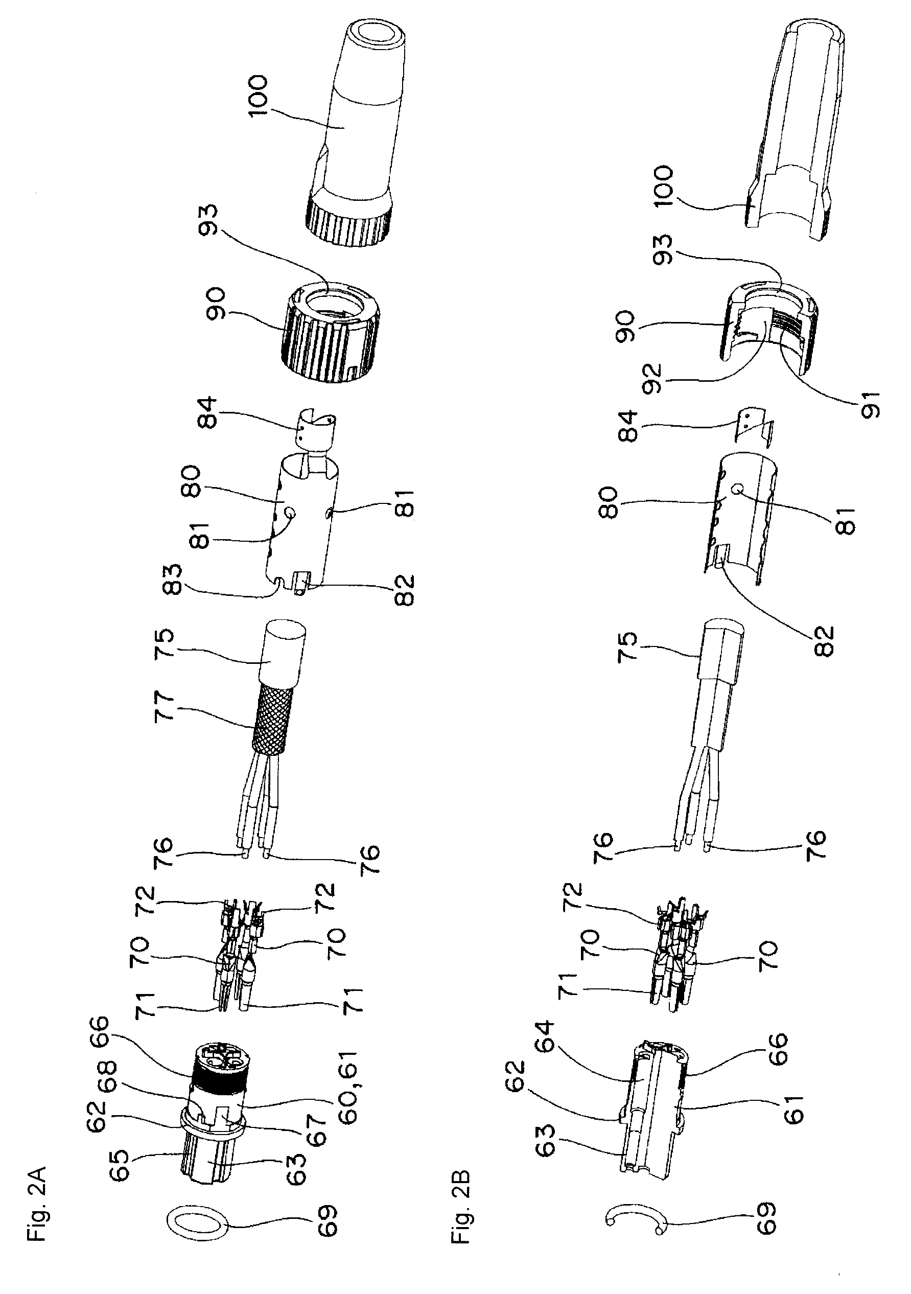
[0073]A second embodiment is a case applied to a connector including the screw-type plug 10 and the socket 60, as shown in FIGS. 12A to 13B.

[0074]As shown in FIGS. 12A and 12B, the screw-type plug 10 has a configuration similar to the bayonet-type plug according to the first embodiment, and thus like reference numbers are denoted for like portions and the description thereof will not be given, and only the different portions will be described in detail.

[0075]The plug 10 according to the second embodiment does not include the slip-out preventing member and the coil spring, and the shape of the plug holder 40 is different. The plug holder 40 has a cylindrical shape capable of fitting into the plug main body 11 in a freely turning manner, where the male screw 41 is formed over the entire outer peripheral surface and the turning operation annular rib 42 is extended from the edge on one end side of the outer peripheral surface.

[0076]The method for assembling the screw-type plug 10 is sub...


PUM


Abstract

A connector has a plug connected to a first electric cable, and having a pin terminal and a plug holder, a socket connected to a second electric cable, and having a socket terminal and a socket holder, and a first tubular shield member and a second tubular shield member. The pin terminal of the plug is press-fitted and electrically connected to the socket terminal of the socket. The plug holder is connected to the socket holder. A first end of the first tubular shield member is electrically connected to a shield wire of the first electric cable. An elastic arm formed at an opening edge at a second end of the first tubular shield member is contacted to a conductive inner peripheral surface of the plug holder. A first end of the second tubular shield member is electrically connected to a shield wire of the second electric cable. An elastic arm of formed at an opening edge a second end of the second tubular shield member is contacted to a conductive inner peripheral surface of the socket holder.

Description

BACKGROUND OF THE INVENTION[0001]1. Technical Field[0002]The present invention relates to connectors, and in particular, to a connector having a shield function for shielding the entering of external signals.[0003]2. Related Art[0004]Conventionally, a screw-type connector (see Japanese Unexamined Patent Publication No. 2002-237348) for electrically connecting electric cables on the same axis center by way of a screw has been known for a connector, but the screw-type connector may loosen when microscopic vibration and the like is applied, and torque management is always necessary, whereby maintenance becomes troublesome.[0005]A so-called bayonet-type connector (see Japanese Unexamined Patent Publication No. 2001-52821) has been known as a connector for resolving such a drawback.SUMMARY[0006]However, in both connectors described above, an external signal may enter the electric cable from the connector, and thus an electrical device connected to the relevant electric cable may malfunct...

Claims


Application Information

Patent Timeline
Patent Type & Authority Patents(United States)
IPC IPC(8): H01R9/03
CPCH01R9/037H01R13/6592H01R13/6582H01R13/65917
Inventor HARUNA, TOMOYUKITOMIZU, MOTOYUKIKUMAGAI, JUNICHIROHAYASHI, KAZUKIFUJIWARA, TAIJIROOTSU, NORIHIRO
Owner ORMON CORP
Why Eureka
Try Eureka