Dual frequency band ultrasound transducer arrays

a transducer array and frequency band technology, applied in the direction of transducer types, sound producing devices, using reradiation, etc., to achieve the effect of suppressing the effect of transmitted hf grating lobes

Active Publication Date: 2010-06-01
ANGELSEN BJORN A J +4
View PDF23 Cites 106 Cited by
  • Summary
  • Abstract
  • Description
  • Claims
  • Application Information

AI Technical Summary

Problems solved by technology

1. For the HF pulse to propagate within a range interval of the LF pulse throughout a depth range of the image, the HF and LF radiation surfaces must have a large common area. One generally wants pulse pressures in the HF and the LF pulses in the order of MPa, depending on the application. This requires high electro to acoustic transfer efficiency which with current transducer technology is obtained with resonant operation of the transduction, which in turn gives a limited operative frequency band of current ultrasound transducer arrays, which do not cover the required frequency band (typically 1:5-1:15) for the described applications. Because one needs a large part of the HF and LF radiation surfaces to be common, this wide band presents special challenges for the structural vibration design of the arrays.
2. The large frequency separation between the HF and the LF pulses means that the wave length of the LF pulses is much larger than the wave length of the HF pulses, typically by a factor 5-15, which means that the LF pulse beam is subject to much higher diffractive beam divergence than the HF pulse beam. For adequate collimation of the LF beam to maintain high LF pressures at large depths, one therefore in certain applications needs to use larger width of the LF aperture than the HF aperture. This produces a sliding of the position of the HF pulse relative to the LF pulse with propagation distance, which sets special requirements for the design of the dual frequency radiation surfaces.

Method used


Image

  • Dual frequency band ultrasound transducer arrays
  • Dual frequency band ultrasound transducer arrays
  • Dual frequency band ultrasound transducer arrays

Examples


Embodiment Construction

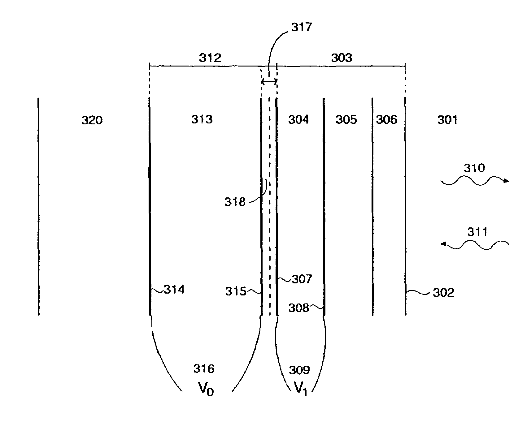
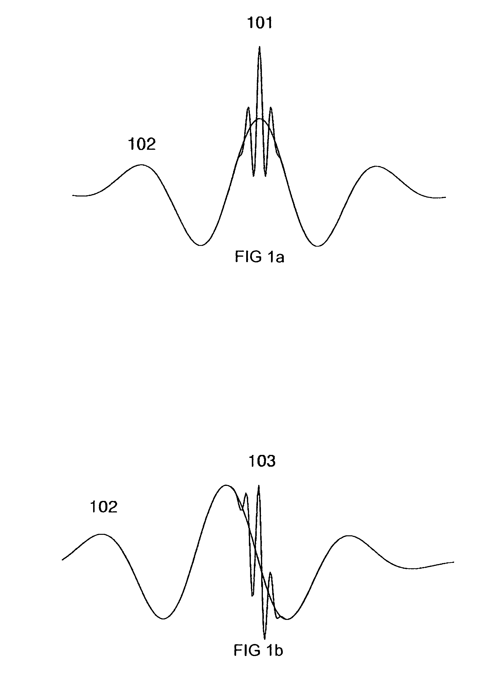
[0032]Example embodiments of the invention will now be described in relation to the drawings. Typical examples of dual frequency pulses that one wants to transmit are shown in FIG. 1 as described above. The challenges in the design of the arrays lie both in the design of the radiation surfaces so that the HF pulse is kept within desired location of the LF pulse for the image range while maintaining adequate amplitude of the LF pulse, and in design of a vibration structure that allows transmission of LF and HF pulses with such wide separation between the frequencies from the same surface.

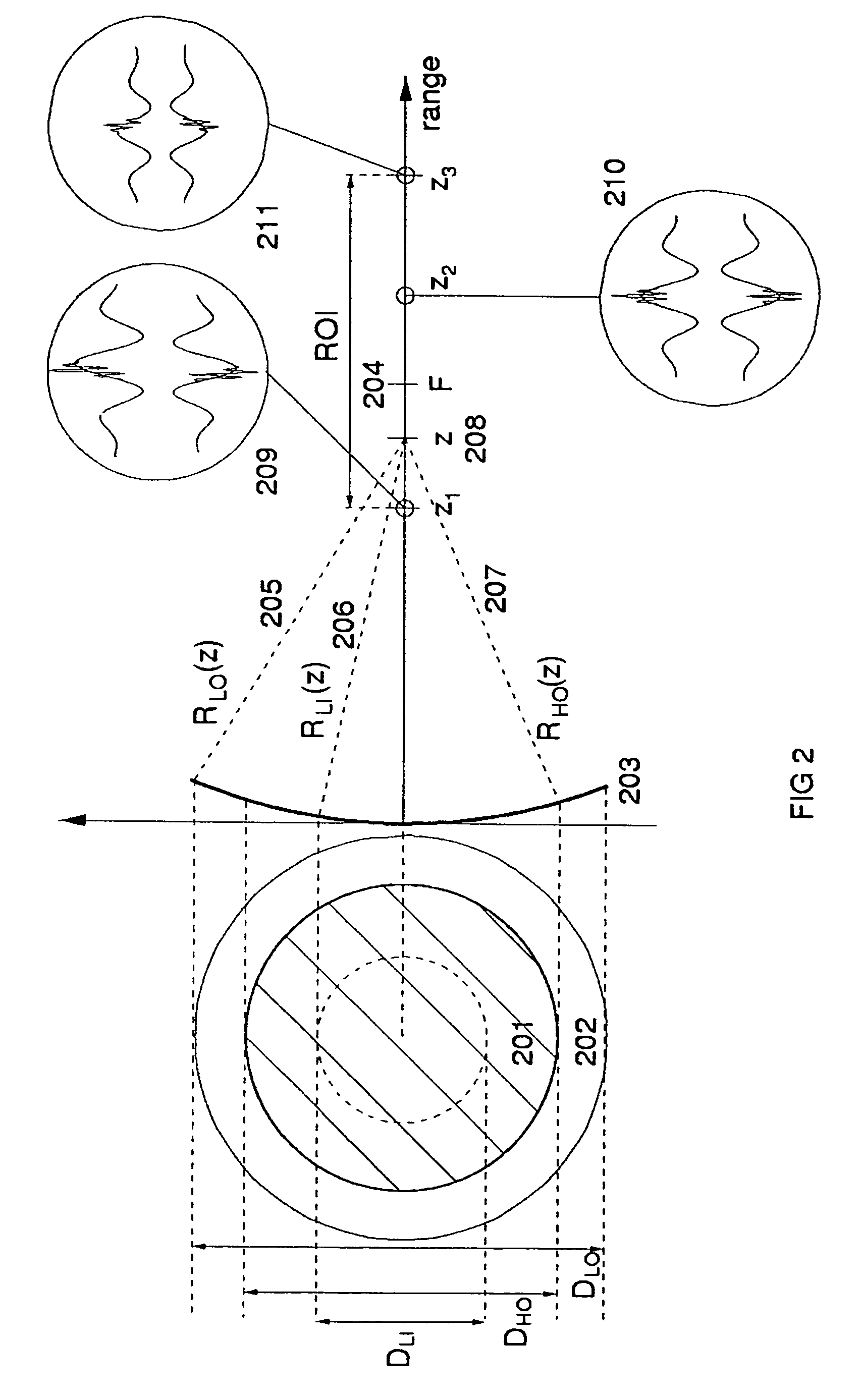
[0033]In some of the applications it is important that the amplitude of the LF pulse at the location of the HF pulse is as high and close to constant as possible throughout the whole imaging range. This requires large apertures of the LF radiation surface to avoid diffraction spread of the LF beam due to the long wave length of the LF pulse compared to the HF pulse. The width of the HF transmission a...


PUM


Abstract

Ultrasound probes that transmits / receives ultrasound pulses with frequencies both in a low frequency (LF) and a high frequency (HF) band, where the radiation surfaces of said HF and LF bands at least have a common region. Several solutions for transmission (and reception) of LF and HF pulses through the same radiation surface are given. The arrays and elements can be of a general type, for example linear phased or switched arrays, or annular arrays or elements with division in both azimuth and elevation direction, like a 1.5D, a 1.75D and a full 2D array. The LF and HF element division and array apertures can also be different.

Description

CROSS REFERENCE TO RELATED APPLICATION[0001]This application claims priority from U.S. Provisional Patent Application Ser. No. 60 / 702,423 which was filed on Jul. 26, 2005.BACKGROUND OF THE INVENTION[0002]1. Field of the Invention[0003]The present invention is directed to technology and designs of efficient acoustic (sonic and ultrasonic) bulk wave transducers for simultaneous operation in at least two frequency bands. Applications of the transducers are for example, but not limited to: medical ultrasound imaging, nondestructive testing, industrial and biological inspections, geological applications, and SONAR applications.[0004]2. Description of the Related Art[0005]The utilization of the nonlinear elasticity of tissue and ultrasound contrast agent micro-bubbles in medical ultrasound imaging provides improved images with less noise. The widest use is in the so-called harmonic imaging, where the 2nd harmonic component of the transmitted frequency band is used for the imaging. A use o...

Claims


Application Information

Patent Timeline
Patent Type & Authority Patents(United States)
IPC IPC(8): A61B8/00H01L41/00H04R19/00
CPCB06B1/064G01S15/8952G01S15/8915G01S7/52022
Inventor ANGELSEN, BJORN A. J.JOHANSEN, TONNI F.HANSEN, RUNEMAASOEY, SVEIN-ERIKNASHOLM, PETER
Owner ANGELSEN BJORN A J
Why Eureka
Try Eureka