Antenna device for radio telephones

an antenna device and radio telephone technology, applied in the direction of antenna supports/mountings, electrical equipment, radiating element structure forms, etc., can solve the problems of increasing the distance between the head of the user of the radio telephone in question and the antenna device of the telephone, increasing the cost of manufacture and complex assembly,

Active Publication Date: 2010-06-01
GIGASET COMMUNICATIONS
View PDF16 Cites 0 Cited by
  • Summary
  • Abstract
  • Description
  • Claims
  • Application Information

AI Technical Summary

Benefits of technology

[0021]One possible object, on the basis of an antenna device of a type described in the introduction, is to improve the antenna device technically in such a manner that it is economical and simple to produce, that it has a high degree of efficiency but nevertheless ensures that the user of the radio telephone in question is less exposed to the effects of electromagnetic radiation and the parasitic interference of the telephone caused by the user is reduced.
[0023]This type of antenna device for radio telephones combines the cost-effective aspect and the advantageous aspect of ease of manufacture of printed circuit board antennas with the advantages of an increased distance between the strip conductor used as the antenna and the head of a user of the radio telephone. As a result of this increased distance, the technical effect on a user during operation of the antenna are reduced. On the other hand, the parasitic interference of the antenna caused by the user is also reduced, such that the efficiency of the antenna is in turn increased as a result.
[0024]The manufacture of a printed circuit board antenna in general and particularly the manufacture of the printed circuit board antenna are simple because the manufacture of the printed circuit board antenna can be integrated into the production process for printed circuit board manufacture. No additional parts that are complex to assemble are required. This thereby saves additional material and the resources required to equip it, for which a special pick and place machine may even be necessary under certain circumstances. Through the savings made by not using a special pick and place machine for example, it is also possible to save on cycle time during production.
[0026]The advantage of the device is that no separate work step is required in order to deflect the region of the strip conductor carrier, carrying the strip conductor used as the antenna, out of the plane of the other regions of the strip conductor carrier before the strip conductor carrier is mounted in the radio telephone. This is accomplished automatically by corresponding and appropriately arranged supporting elements in the radio telephone when the strip conductor carrier is mounted in the radio telephone. Due to the fact that the deflection of the region of the strip conductor carrier, on which the strip conductor used as the antenna is situated, is effected with a reversibly sprung restoring force, a situation resulting in the formation of cracks or even breaks in the strip conductor used as the antenna is avoided.

Problems solved by technology

Although such an antenna device represents an optimum solution in terms of antenna technology, this solution is however no longer acceptable today in practical terms at least in the mass market for reasons of design.
Compared with an arrangement of the antenna device on the same plane as the aforementioned carrier this results in an increased distance between the head of a user of the radio telephone in question and the antenna device of this telephone.
One disadvantage of such an antenna device is the fact that an additional component is used for the antenna, which is expensive to manufacture and complex to assemble.
One important disadvantage of this antenna device is the fact that the distance from the strip conductor used as the antenna to an outer wall of the associated radio telephone and thus to the head of a user of said radio telephone is very small.
Here too this small distance between radio telephone and head again causes an undesired distortion of the radiation pattern of the antenna device of the telephone in addition to increased exposure of the head of a user of the radio telephone to the electromagnetic radiation emitted by the telephone.
As a result, radiation losses due to absorption are again caused which are reflected in a reduced range of the telephone.
To compensate for this would mean increasing the radiated power, which in turn results in increased irradiation of high-frequency power into the head of the user.

Method used


Image

  • Antenna device for radio telephones
  • Antenna device for radio telephones
  • Antenna device for radio telephones

Examples


Embodiment Construction

[0033]Reference will now be made in detail to the preferred embodiments of the present invention, examples of which are illustrated in the accompanying drawings, wherein like reference numerals refer to like elements throughout.

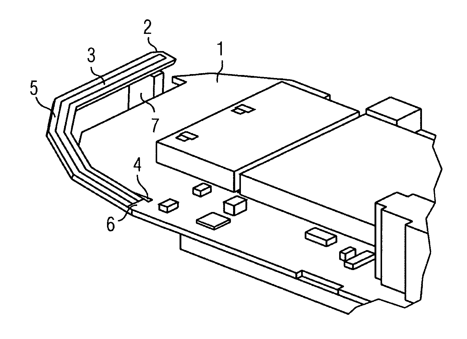
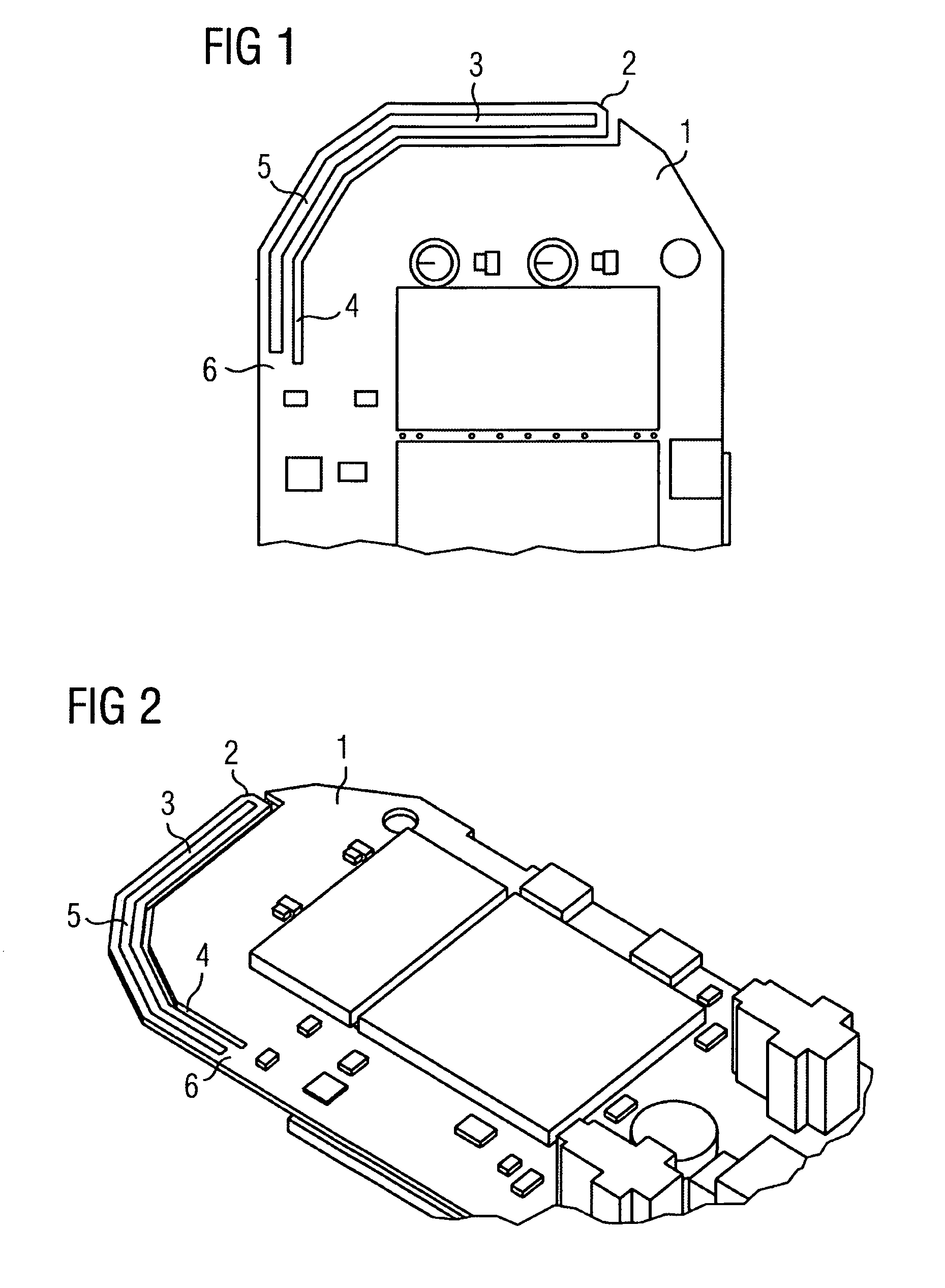
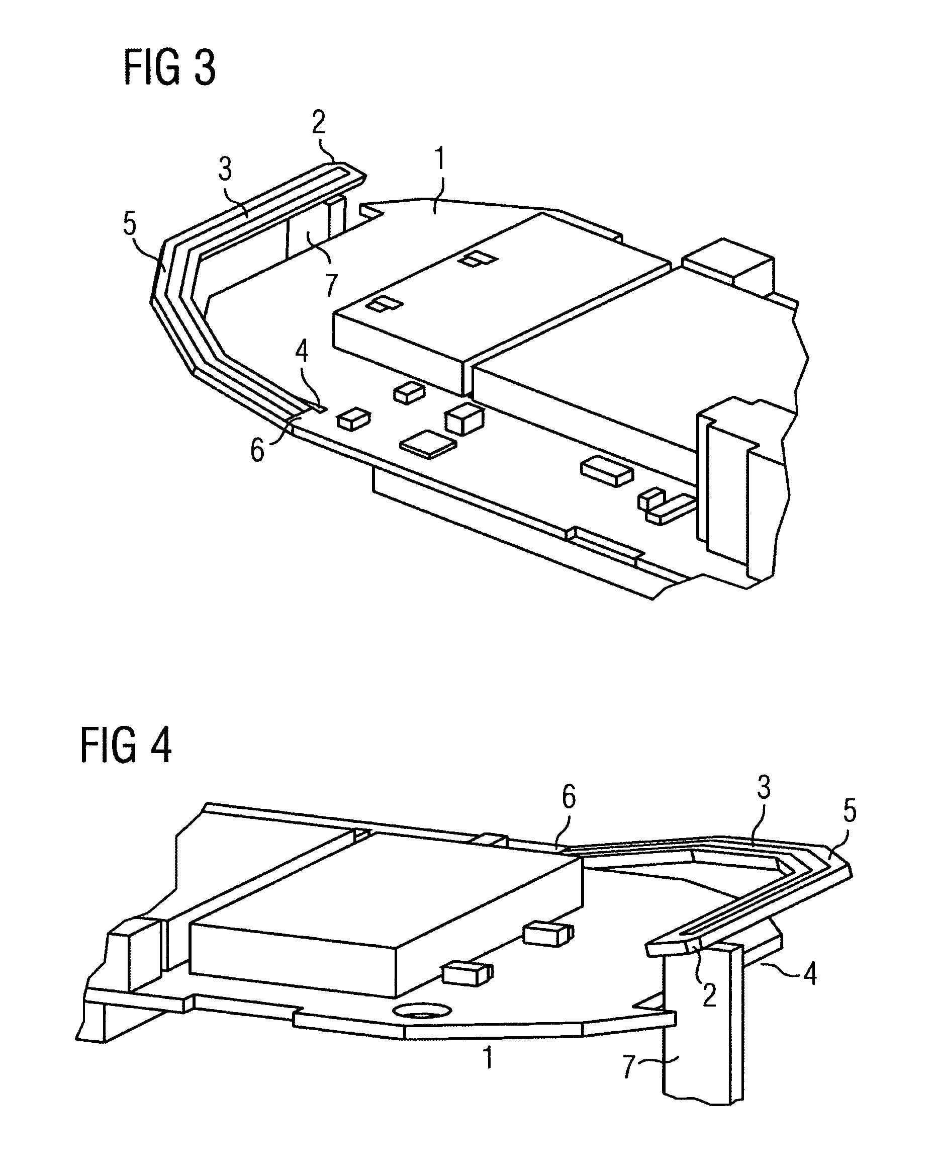
[0034]As illustrated by FIGS. 1 and 2, the strip conductor carrier 1 for a radio telephone (not shown in more detail in the figures) has an antenna device 2 which is arranged at one edge of the strip conductor carrier 1. The antenna device 2 includes a strip conductor 3 which forms the actual antenna. The strip conductor carrier 1 is partially machined away with an open-ended cut 4 around the strip conductor 3 acting as the antenna. In this manner a flexible part 5 is obtained, on which the strip conductor 3 used as the antenna is located. Given an appropriate choice of material for the strip conductor carrier 1, this part is sufficiently tensile and thus be pushed into any position. The open-ended cut 4 is chosen such that a segment 6 still remains to attach...


PUM


Abstract

An antenna device for radio telephone based on a printed circuit board antenna or a strip conductor antenna and simple to produce and has a high efficiency, but nevertheless ensures that the user of the radio telephone is less exposed to the effects of electromagnetic radiation and the parasitic interference of the telephone caused by the user is reduced. To this end, the strip conductor carrier is cut around strip conductors used as the antenna up to a section used for the connection of the strip conductor used as the antenna to the other strip conductors of the strip conductor carrier. Furthermore, at least when the strip conductor carrier is mounted in the radio telephone, the cut-out regions of the strip conductor carrier, carrying the strip conductor used as the antenna is deflected out of the plane of the other regions of the strip conductor carrier.

Description

CROSS REFERENCE TO RELATED APPLICATIONS[0001]This application is based on and hereby claims priority to PCT / EP2006 / 061555, filed Apr. 12, 2006 and to German Application No. 10 2005 030 384.6 filed on Jun. 29, 2005, the contents of which are hereby incorporated by reference.BACKGROUND OF THE INVENTION[0002]The invention relates to an antenna device for radio telephones.[0003]Radio telephones have an antenna, with the aid of which a wireless connection can be established with corresponding associated transmitter / receiver stations.[0004]Basically there are three possible ways of implementing antennas in a radio telephone.[0005]Firstly, it is possible to use an additional external component as the antenna.[0006]Such an implementation is known for example from the document DE 696 22 451 T2.[0007]The antenna device implemented in accordance with this document comprises an additional antenna component which is brought out from the housing of the radio telephone in question.[0008]Although s...

Claims


Application Information

Patent Timeline
Patent Type & Authority Patents(United States)
IPC IPC(8): H01Q1/24
CPCH01Q1/243H01Q1/38H01Q1/245
Inventor GAPSKI, DIETMARHERRMANN, STEPHAN
Owner GIGASET COMMUNICATIONS
Why Eureka
Try Eureka