Recording method for dye-based recordable DVD medium and recording apparatus

a dye-based recordable and dvd medium technology, applied in the field of dye-based recordable dvd medium recording method, can solve the problems of uniform mark width, jitter value is higher, and the condition of marks and spaces to be formed is changed at different recording linear velocities, so as to achieve efficient widening of recording power margin, jitter rate and error rate can be reduced, and the effect of convenient application

Inactive Publication Date: 2010-06-01
RICOH KK
View PDF20 Cites 3 Cited by
  • Summary
  • Abstract
  • Description
  • Claims
  • Application Information

AI Technical Summary

Benefits of technology

[0010]The present invention aims to provide a recording method and a recording apparatus that allow for obtaining a favorable recording waveform when recording information on a dye-based recording DVD medium at high speed.
[0015]According to the present invention, it is possible to efficiently widen a recording power margin (an allowable recording power range) by which recording properties such as jitter rate and error rate can be lowered, at any recording linear velocities. The recording method of the present invention can be easily applied to dye-based recordable DVD media. The recording method for dye-based recordable DVD medium and the recording apparatus of the present invention also allow for recording information on dye-based recordable DVD media each of which has a substantially same format as those of CD-R recording media or CD-RW recording media that are presently mass-produced.

Problems solved by technology

Typically, in a dye-based recordable DVD medium where pits (marks) are formed by use of heat mode, the pulse width and the recording power of a recording pulse train are optimized by emission of a laser during recording at a specific recording speed, thus there exist a problem that the condition of marks and spaces to be formed is changed at different recording linear velocities.
In other words, dye-based recordable DVD media suffer from problems that the jitter values tend to be higher, because thermal capacity of leading heating pulses required to form marks turns into insufficient, and the heating temperatures are varied relative to the optimal decomposing temperature to attain, resulting in variations in average mark lengths, and uniform mark widths cannot be obtained due to varied duty ratio of optimum heating pulse, resulting in thin marks or thick marks formed depending on the mark lengths.
According to the format, there are problems that when a land pre-pit signal (LPPb) is less than 0.16, pre-pit information such as pre-pit address cannot be properly reproduced; in contrast, when a land pre-pit signal (LPPb) is more than 0.32, the land-pit signal itself behaves noisily at data region, thus resulting in frequent occurrences of data errors.
Accordingly, there is a disadvantage that the land cut width needs to be finely adjusted to each recording material by the use of a stamper, and the land cut width needs to be adjusted so as to control the land pre-pit signal within the range of 0.16 to 0.32.

Method used


Image

  • Recording method for dye-based recordable DVD medium and recording apparatus
  • Recording method for dye-based recordable DVD medium and recording apparatus
  • Recording method for dye-based recordable DVD medium and recording apparatus

Examples


example 8

[0133]EFM signals (minimum pit length=about 0.4 μm) were recorded on the following various optical recording media at a recording speed of 12× with varying the value “b” (the value “a” was fixed to 0.01), and the jitter values of the respective optical recording media were measured. Table 4 shows the measurement results. The values (%) shown in Table 4 are jitter values when recording the signals at a recording speed of 12× with the optimum recording power.

[0134]As is shown in Table 4, the optimum value “b” varied depending on the type of optical recording medium, and the minimum jitter value could be obtained with the value “b” of 1.3 or more.

[0135]Medium 1: DVD+R manufactured by Ricoh Company Ltd.

[0136]Medium 2: DVD+R manufactured by TDK Corp.

[0137]Medium 3: DVD-R manufactured by Fuji Film Corp.

[0138]Medium 4: DVD-R manufactured by RiTEK Corp.

[0139]

TABLE 4b value1.21.31.41.5Medium 110.4%9.2%8.0%6.7%Medium 27.4%6.8%6.8%7.2%Medium 38.3%7.5%6.8%6.8%Medium 49.5%8.3%7.1%7.0%

example 9

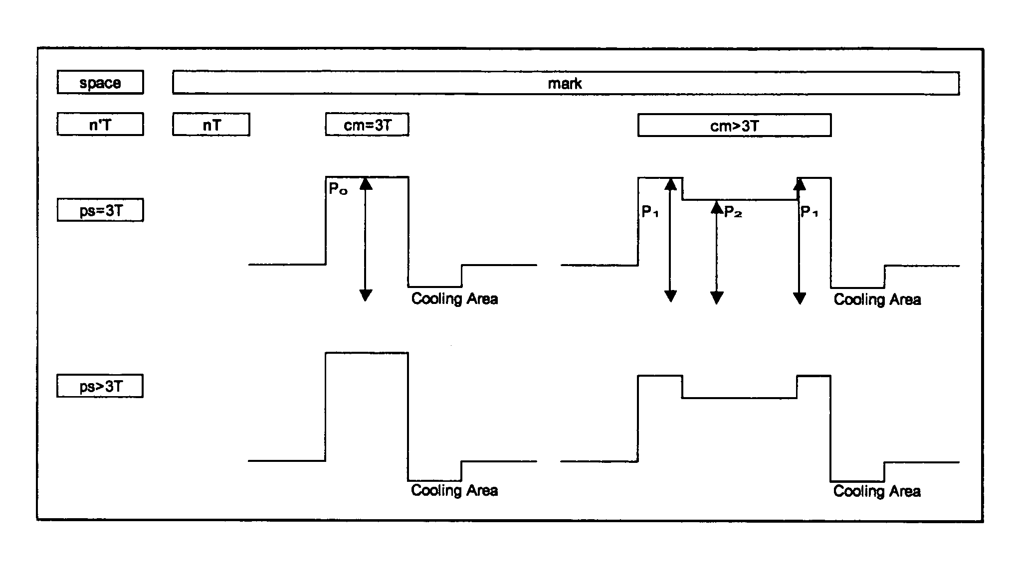
[0140]EFM signals (minimum pit length=about 0.4 μm) were recorded on the optical recording medium used in Example 1 at a recording speed of 8× (27.9 m / s) in accordance with the recording waveform shown in FIG. 4 with varying the value “b” (the value “a” was fixed to 0 (zero)), varying the recording powers P1 and P2 for Comparative Examples 1 to 3 as described below and keeping the P1 / P2 ratio constant to thereby check the recording properties relative to the recording power.

[0141]Comparative Example 1: a=0; b=1.5 (same as Comparative Example 1 shown in FIG. 7)

[0142]Comparative Example 2: a=0; b=1.6

[0143]Comparative Example 3: a=0; b=1.4

[0144]As shown in FIG. 8, with the P1 / P2 ratio kept constant (a=0), both the minimum jitter value and the recording power margin could not be obtained even when the value “b” was varied. However, when the recording power ratio of Comparative Example 3 (b: small) is used at a high recording power region (22.5 mW or more), the recording power ratio of C...


PUM

PropertyMeasurementUnit
wavelengthaaaaaaaaaa
decomposition temperatureaaaaaaaaaa
wavelengthaaaaaaaaaa

Abstract

A recording method for dye-based recordable DVD medium which includes recording shortest marks on a recording layer primarily containing an organic dye using a simple rectangular wave pulse; recording marks each having the second shortest or still longer mark length using one pulse of which the front and rear edges are highly energized for a given time; and controlling the optical energy for irradiating rear edge or backward of the pulse with a cooling pulse to be 0.1 mW or less for a given time, wherein when the recording power of the front and rear edges of the respective pulses is represented by P1 and the recording power of intermediate pulse between the pulse front edge and the pulse rear edge is represented by P2, P1 / P2 is set to be greater when P1 is a low power, and P1 / P2 is set to be smaller when P1 is a high power.

Description

BACKGROUND OF THE INVENTION[0001]1. Field of the Invention[0002]The present invention relates to a recording method for dye-based recordable DVD medium in which information can be recoded and additionally recorded by irradiating a dye-based recordable DVD medium with a light beam to induce optical changes such as transmittance and reflectance to the recording layer thereof, and also relates to a recording apparatus.[0003]2. Description of the Related Art[0004]Presently, recordable digital versatile discs (DVD-R) are developed as next-generation large capacity optical discs. As essential technologies to enhance recording capacity of optical discs, it is necessary to develop recording materials to micronize recording pits, to employ image compression formatting technologies as typified by MPEG2, and to develop technologies for shortening the wavelength of semiconductor lasers for reading recording pits.[0005]Conventionally, as for semiconductor lasers of the red wavelength region, onl...

Claims


Application Information

Patent Timeline
Patent Type & Authority Patents(United States)
IPC IPC(8): G11B20/10
CPCG11B7/00456G11B7/246
Inventor ISHIMI, TOMOMI
Owner RICOH KK
Why Eureka
Try Eureka