
Method for correcting an image data set, and method for generating an image corrected thereby

a technology of image data and generating method, which is applied in the field of generating image correction thereby, can solve the problems of sensitivity dynamic range, significant quality limitations of image data set, and rapid saturation of incident radiation energy with increasing incident radiation energy, and achieve the effect of improving the generation of imag

Inactive Publication Date: 2010-06-01
SIEMENS HEALTHCARE GMBH
View PDF5 Cites 10 Cited by
  • Summary
  • Abstract
  • Description
  • Claims
  • Application Information

AI Technical Summary

Benefits of technology

The present invention provides a method for correction of image data sets that was acquired with a planar image detector that has different dynamic ranges. The method calibrates the detector at different radiation doses to cover the entire dynamic range. The calibration images are used to generate a correction factor for each detector pixel, which is used to correct the image intensity values of the pixels. The method compensates for the different sensitivities of the detector pixels by using the global intensity average of the calibration images and the intensity value of the corresponding pixel. The dark image of the detector is subtracted from the image data set to remove interfering contributions. The correction factor is determined using the quotient from the global intensity average of the calibration image and the intensity value of the corresponding pixel. The method improves the quality of the image data set and allows for a better generation of an image from the raw data.

Problems solved by technology

This characteristic grayscale value distribution is reflected in an image data set of a subject that has been acquired and can lead to significant quality limitations of the image data set.
The high-sensitivity dynamic range supplies usable signals even at lower energy of the incident radiation, but is rapidly saturated with increasing incident radiation energy.
The low-sensitivity dynamic range is saturated only at significantly higher radiation energy, however supplies noisy and therewith unusable signals at low radiation energy.
The calibration of such a planar image detector requires a certain technical effort.
If the calibration was implemented at a single radiation dose and the image of this was acquired at a radiation energy range deviating from said single radiation dose, the calibration may be insufficient.

Method used


Image

  • Method for correcting an image data set, and method for generating an image corrected thereby
  • Method for correcting an image data set, and method for generating an image corrected thereby
  • Method for correcting an image data set, and method for generating an image corrected thereby

Examples


Embodiment Construction

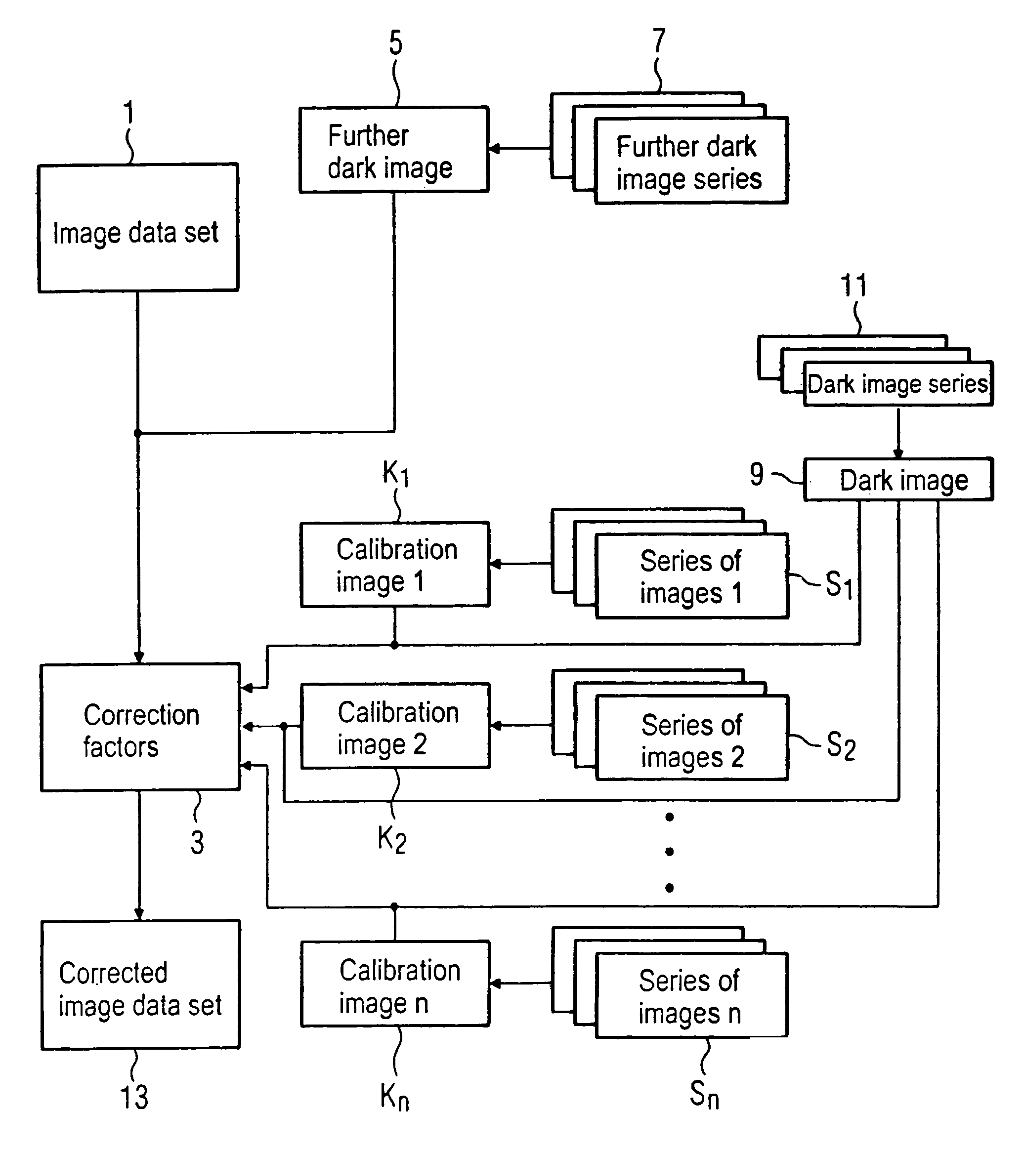
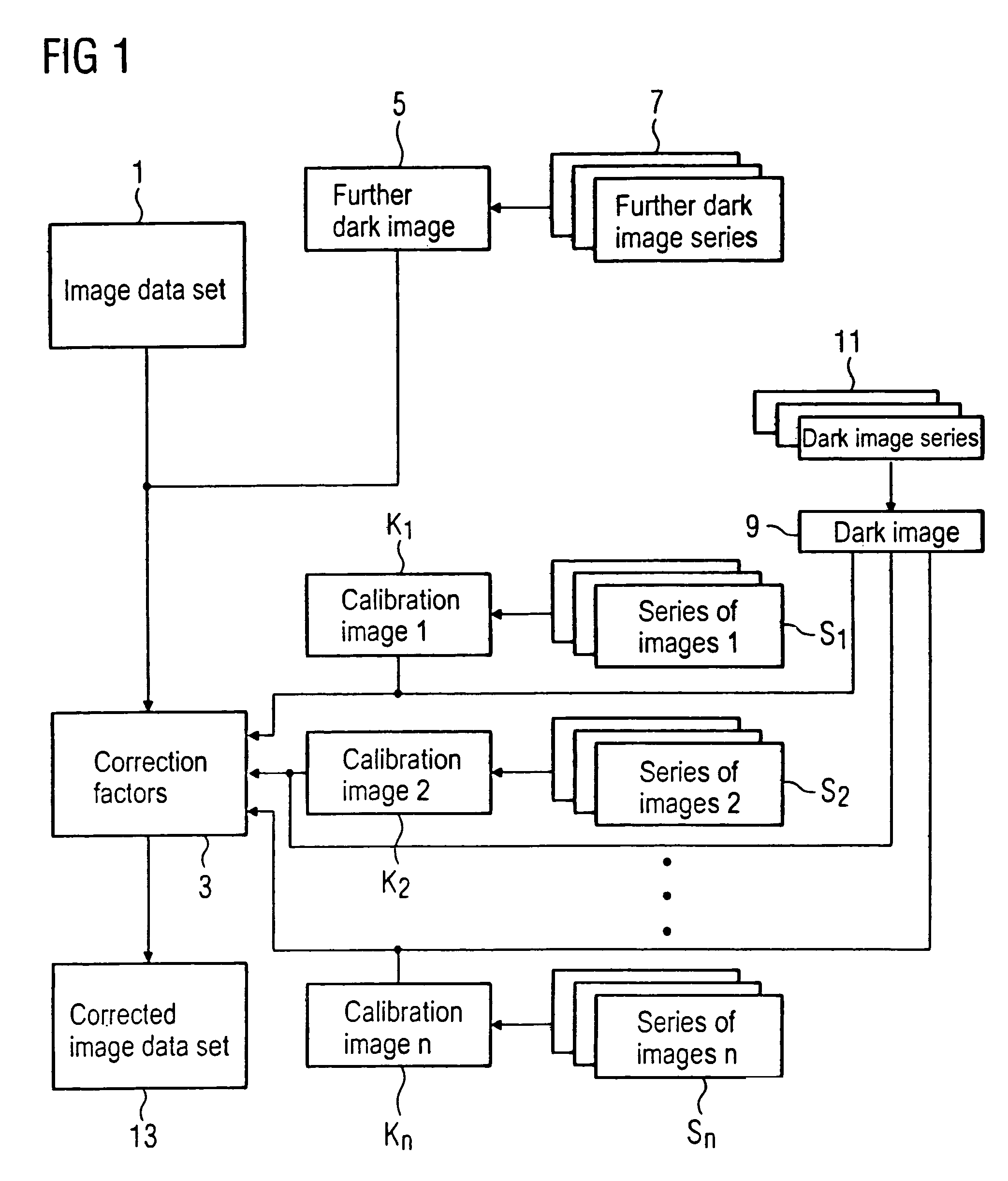
[0066]A method for correction of an image data set 1 that was acquired with a planar image detector is explained in FIG. 1 using a block diagram. In an actual image correction method the pixels of the image data set 1 (in which a subject was acquired with the planar image detector and the pixels of which exhibit different image intensity values) are multiplied with respectively one correction factor 3 in order to obtain a corrected image data set 13. In this correction method the different sensitivities of the individual detector pixels are compensated.

[0067]The correction factors 3 necessary for this are determined with the aid of a plurality of calibration images K1, K2 . . . Kn that were acquired in a preliminary process. The calibration images K1, K2 . . . Kn are thereby what are known as light images, i.e. images in which the planar image detector is exposed without a subject in the beam path absorbing x-rays. The different calibration images K1, K2 . . . Kn have thereby been a...


PUM


Abstract

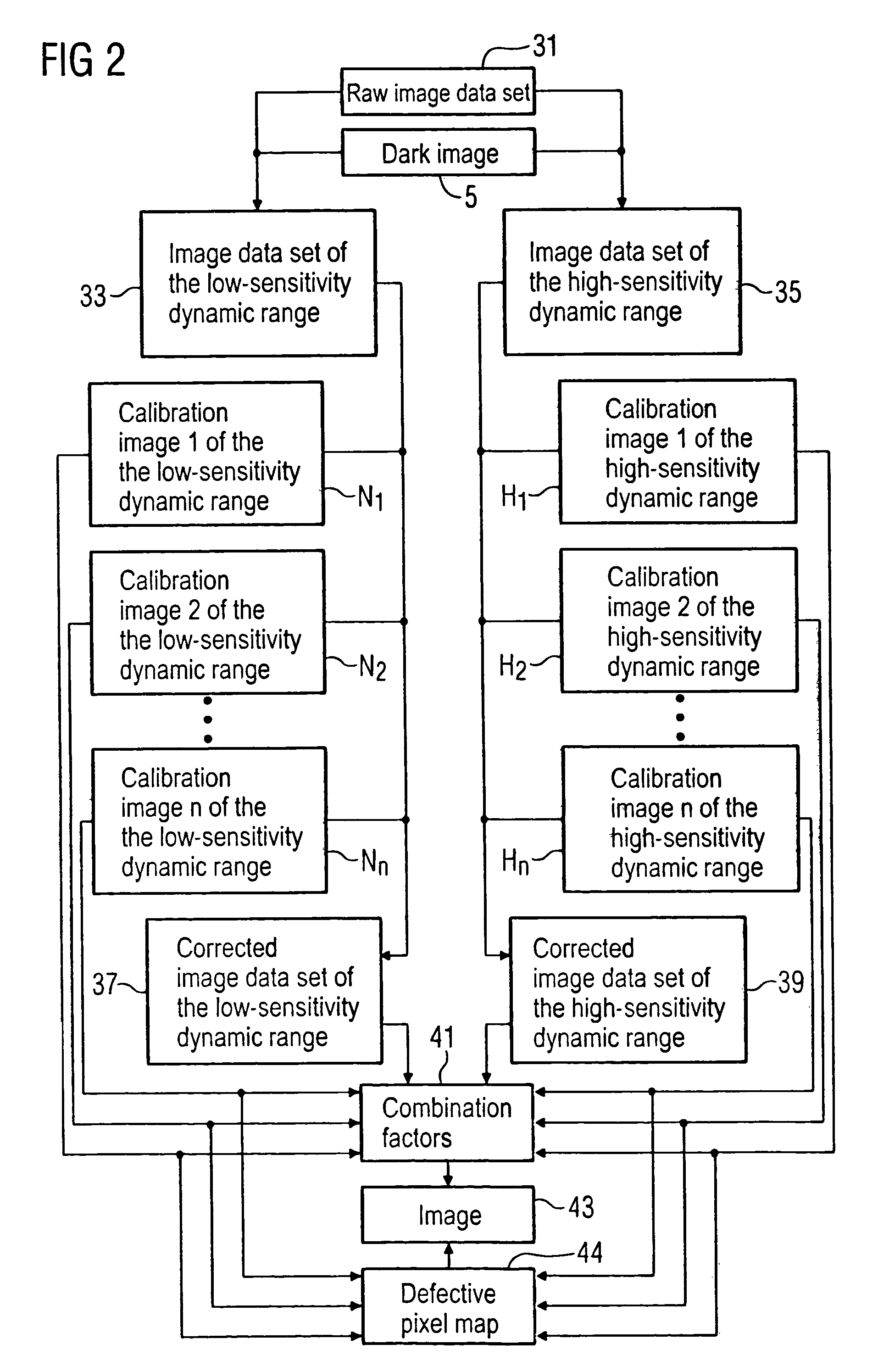
In a method for correction of an image data set that was acquired with a planar image detector using at least two calibration images that were acquired in a preliminary procedure, as well as a method for generation of an image from a raw image data set that was acquired with a planar image detector with a high-sensitivity dynamic range and with a low-sensitivity dynamic range and which is composed of two image data sets, of which one was acquired in the high-sensitivity dynamic range and the other was acquired in the low-sensitivity dynamic range, at least two calibration images are generated in each dynamic range in a preliminary process. These calibration images are used in a correction procedure for the correction of the individual image data sets, as well as in a combination procedure to merge the two corrected image data sets into one image. In the combination procedure the two image data sets are conformed to one another using a comparison of the calibration images of the high-sensitivity dynamic range with the calibration images of the low-sensitivity dynamic range. The adjusted, corrected image data sets are added with weighting in a second step.

Description

BACKGROUND OF THE INVENTION[0001]1. Field of the Invention[0002]The present invention concerns a method for correction of an image data set that has been acquired with a planar image detector, as well as a method for generation of an image from a raw image data set that was acquired with a planar image detector with two dynamic ranges.[0003]2. Description of the Prior Art[0004]An image that is acquired with an x-ray planar image detector without x-ray-absorbing subjects being located in the beam path (known as a light image) does not exhibit a homogeneous grayscale value distribution but instead shows a characteristic brightness curve. This is due to different causes that are based on specific properties of the detector pixels as well as curves based on the specific properties of the x-ray radiation generated by an x-ray radiator.[0005]Even without exposure, every detector pixel also produces a specific dark current that is primarily temperature-dependent. Furthermore, each detector...

Claims


Application Information

Patent Timeline
Patent Type & Authority Patents(United States)
IPC IPC(8): G06K9/00
CPCG06T5/50G06T5/007H04N5/2355H04N5/325H04N5/235G06T2207/10116G06T2207/30004H04N23/70H04N23/741G06T5/90
Inventor MASCHAUER, STEFANRITTER, DIETERSCHMIDGUNST, CHRISTIAN
Owner SIEMENS HEALTHCARE GMBH
Learn More