Collapsable screen and design method

a technology of collapsible partitions and screens, applied in the direction of shutters/movable grilles, door/window protective devices, draperies, etc., can solve the problems of cost, labor-intensive and thus costly production of draperies and roman-type shades made of textiles, and the cost of roll-up shades is generally not solved

Active Publication Date: 2010-06-08
PEREIRA CARLOS E
View PDF30 Cites 48 Cited by
  • Summary
  • Abstract
  • Description
  • Claims
  • Application Information

AI Technical Summary

Problems solved by technology

Toti recognizes that “the great objection to the use of Venetian blinds in artistic homes and buildings is that they contribute a barred window effect which is jail-like in its mechanical precision” which is overcome by Toti's undulating, rather than rigid, slats.
Curtains and Roman-type shades made of textiles are generally labor-intensive and thus costly to produce.
Roll-up shades usually add little aesthetic effect to their surrounding environment, except for that contributed by the textile from which it is made.
The rarity of such structures in commerce today might show that they rely on material strength characteristics that go beyond what is possible in a sufficiently large dimension, or that problems associated with cost remain unsolved.
Also, such models gain rigidity through folding, but they do not gain stability; their stability is largely dependent on their anchor points on the ground.

Method used


Image

  • Collapsable screen and design method
  • Collapsable screen and design method
  • Collapsable screen and design method

Examples


first embodiment

FIGS. 1-8

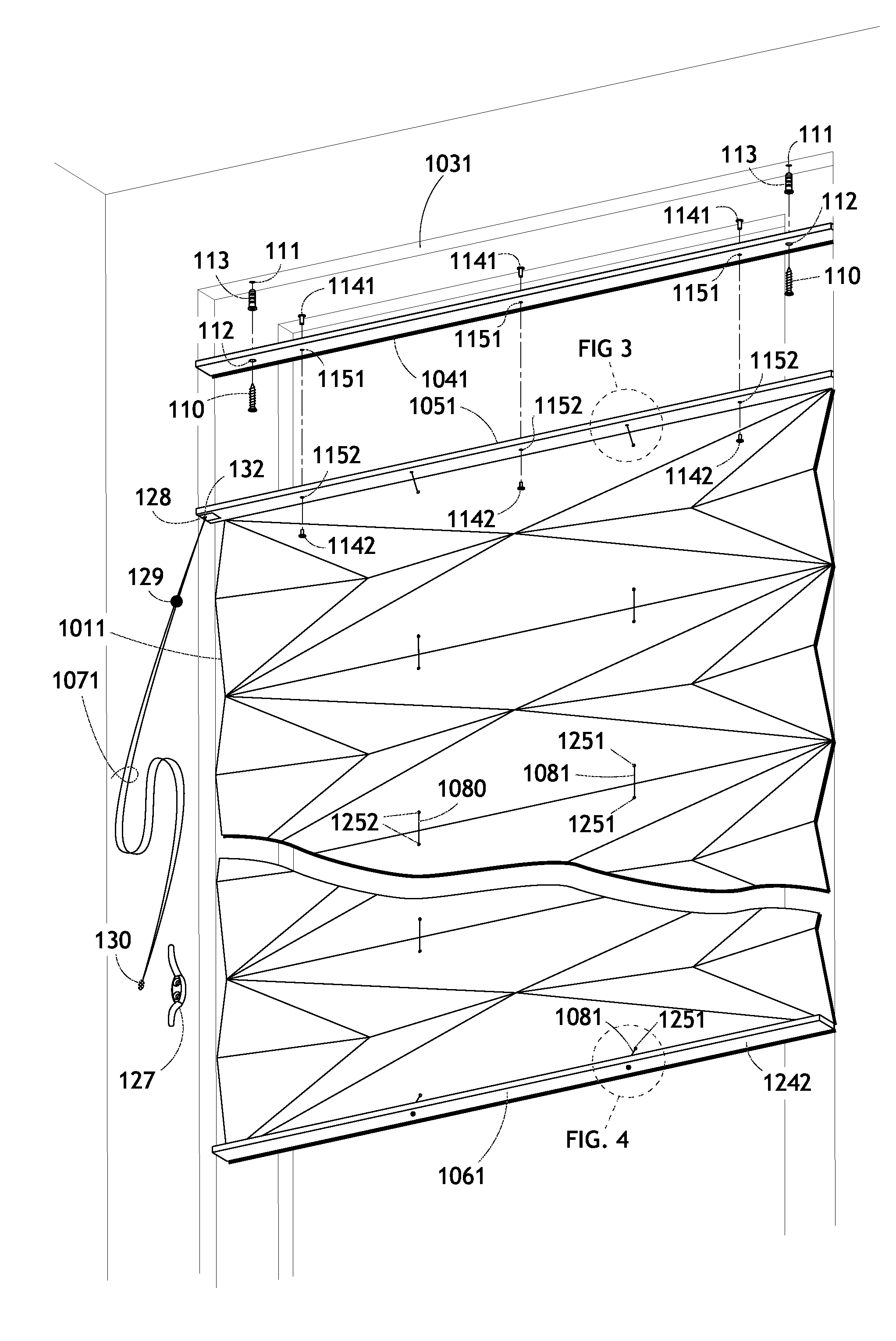
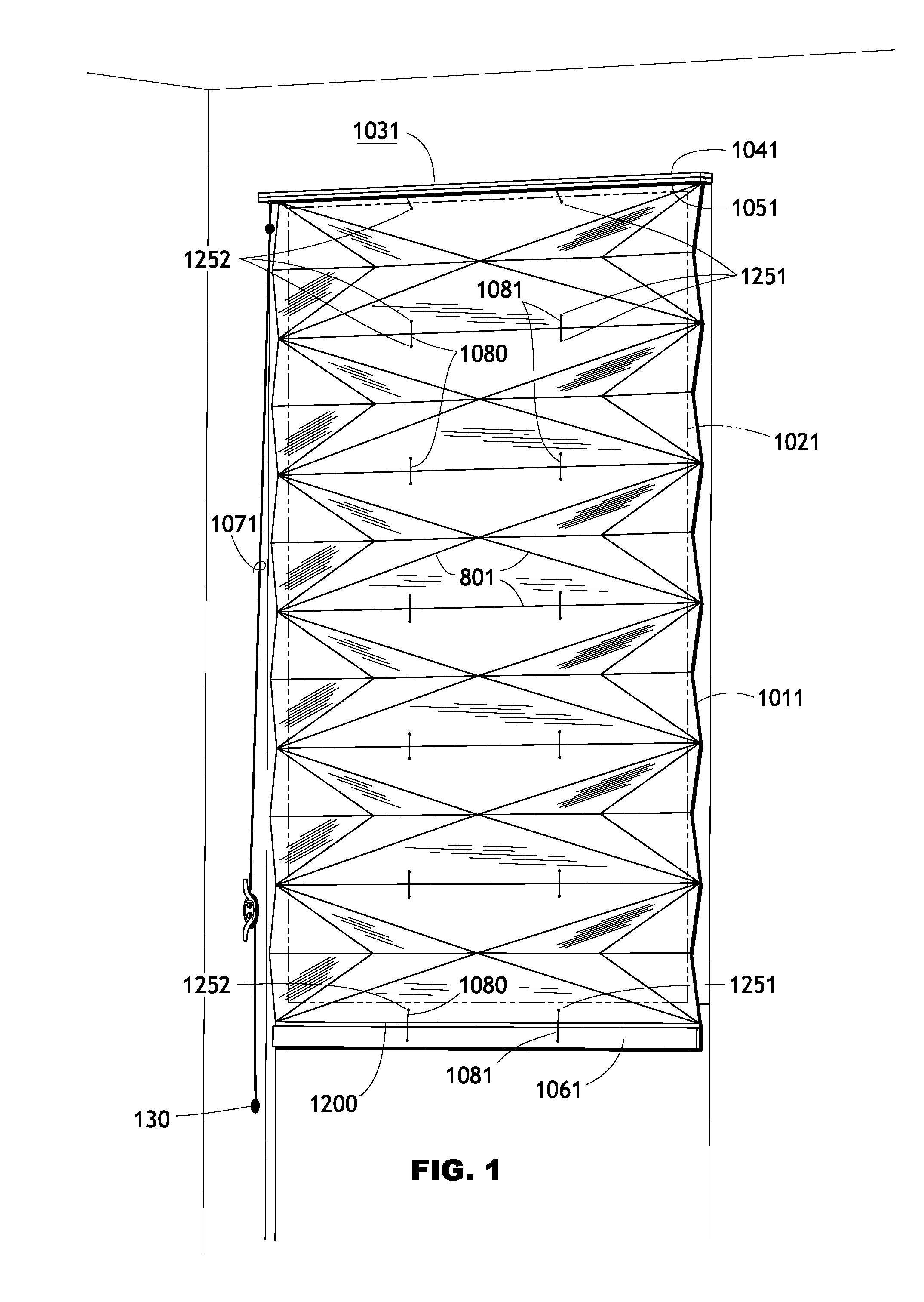
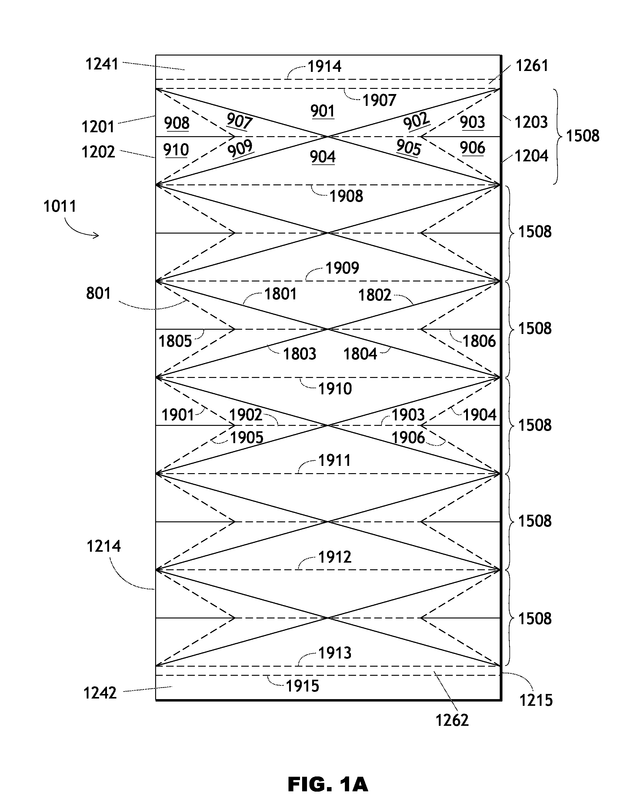
[0146]FIG. 1 shows a perspective view of a first embodiment in its fully expanded, or lowered, state. A collapsible material 1011, forming a light-controlling device, covers or occupies a theoretical base area 1021 (indicated by a long-dashed rectangle) and hides the base area from view if the material is opaque, or somewhat obscures the base area if the material is translucent or transparent, when the collapsible material is in its fully expanded state. The base area can be for example a rectangle corresponding to and slightly offset from the panes of a window. In this embodiment the base area 1021 is several centimeters smaller in each dimension than the boundary of the collapsible material 1011.

Description of Mounting Device and Means of Operation

[0147]In FIG. 1, the embodiment is attached to the surface 1031 of a window casement, ceiling, window frame, wall, or other relatively immobile structure by way of a mounting device comprising a mounting rail 1041 and an adjacen...

second embodiment

Description—FIGS. 9-9C, 53, 54

[0161]A second embodiment is shown in FIG. 9 in its fully expanded state. In this embodiment, a single pull cord 1072 is present. A bottom rail 1062 is attached to the back side of a panel 921 within a tessellation 802 of panels and folds forming a collapsible material 1012. The pull cord 1072 passes through a series or pattern of holes 1253 and is anchored to the bottom rail 1062 by way of a ferrule or knot 1222. The series of holes causes the pull cord to follow a curved path on the collapsible material 1012. The bottom rail 1062's length is less than the material's full width, as it occupies the length of an edge segment 1205, which is one of three segments forming the bottom edge of the collapsible material.

[0162]In the embodiment's fully collapsed state (perspective view FIG. 9C and plan view FIG. 53), the panel 921 lies parallel to and as near as possible to a top rail 1052, underlying an array of folded panels 920 (visible in FIGS. 53 and 54). In...

third embodiment

Description—FIGS. 10, 55

[0164]In perspective FIG. 10 a third embodiment is shown in its fully expanded state. Each of two symmetrically disposed series of panels in a collapsible material 1013 contain limiting and limited sets of panels, corresponding to a relationship among rigid panels 911-915 in which panels 911 overlap panels 912, panels 912 overlap panels 913, and panels 913 overlap panels 914, and panels 914 overlap panels 915, permanently under normal operating conditions. An operating device comprises a pair of pull cords 1073, which have an arrangement similar to other pull cord embodiments previously described.

[0165]The aforementioned panels are also shown in FIG. 55 in a schematic representation of the collapsible material 1013 comprising the panels of the embodiment. The geometry shown is a tessellation comprising a tessellation module 1502, the module repeated along a vertical axis four times in this Fig. Likewise, sets of tessellation lines 2001-2009 are also repeated,...


PUM


Abstract

Several embodiments of a collapsible screen employing novel folding structures have many possible uses: window shade, room divider, decorative backdrop, wall hanging, and others. A disclosed method allows its user to design many embodiments of the screen. The method incorporates three modifiable sets or databases: a set (220) of patterns, a set (221) of criteria by which a possible embodiment is evaluated for practicability, and a set (222) of transformations which can be applied to the possible embodiment to improve it with respect to the criteria (221). The sets can change to reflect new assumptions, design characteristics, and hardware.

Description

CROSS-REFERENCE TO RELATED APPLICATIONS[0001]NONEFEDERALLY SPONSORED RESEARCH[0002]N / ASEQUENCE LISTING[0003]N / ABACKGROUND[0004]1. Field of Invention[0005]This invention relates to window shades, collapsible partitions, folding screens, and the like.[0006]2. Prior Art[0007]Among the product categories within the window coverings industry are various types of curtains; Roman shades or blinds; Venetian blinds; pleated shades; roll-up or roller shades; vertical blinds; and others. In terms of functional typology, this list can account for almost all the products on the market at present and at any time in the past. This list of categories has remained unchanged for 50 years or more. The most recent category is vertical blinds, which were invented in the 1890s, but were not commercially popular until the 1940s. The rest of the categories have existed for hundreds of years.[0008]Based on a review of prior art, the vast majority of improvements to window coverings have been detail-oriented...

Claims


Application Information

Patent Timeline
Patent Type & Authority Patents(United States)
IPC IPC(8): A47H23/04
CPCE06B9/262E06B2009/2625
Inventor PEREIRA, CARLOS E.
Owner PEREIRA CARLOS E
Why Eureka
Try Eureka