
Active headrest mechanism for vehicle seat

a technology of active headrest and vehicle seat, which is applied in the direction of vehicle components, pedestrian/occupant safety arrangements, vehicle arrangements, etc., can solve the problems of loss of operation reliability deterioration of seat back comfort, etc., and achieves the reduction of seat cushion thickness, reducing the number of parts of active headrest mechanism, and improving the comfort of seat back

Inactive Publication Date: 2010-06-08
TS TECH CO LTD +1
View PDF43 Cites 17 Cited by
  • Summary
  • Abstract
  • Description
  • Claims
  • Application Information

AI Technical Summary

Benefits of technology

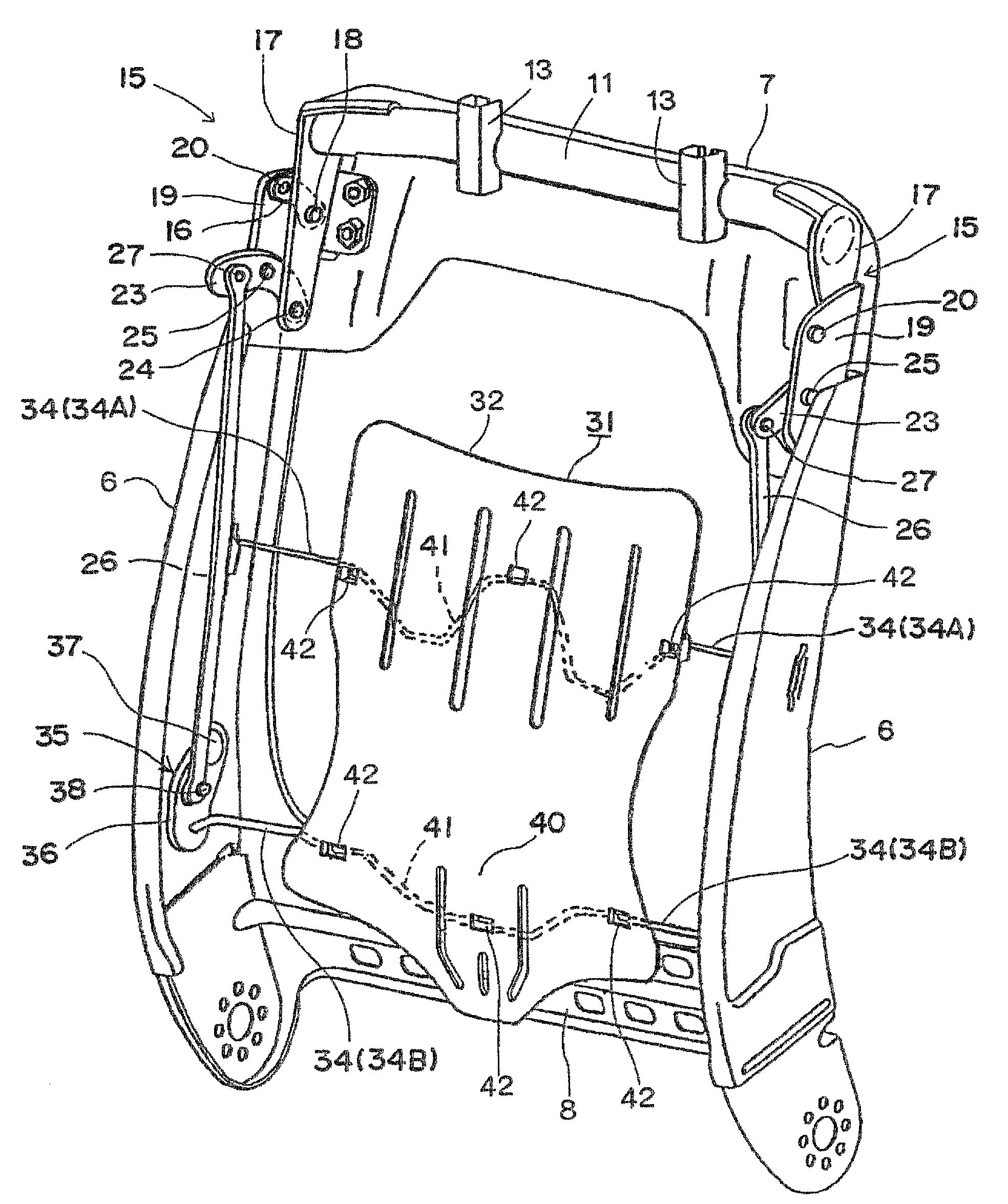
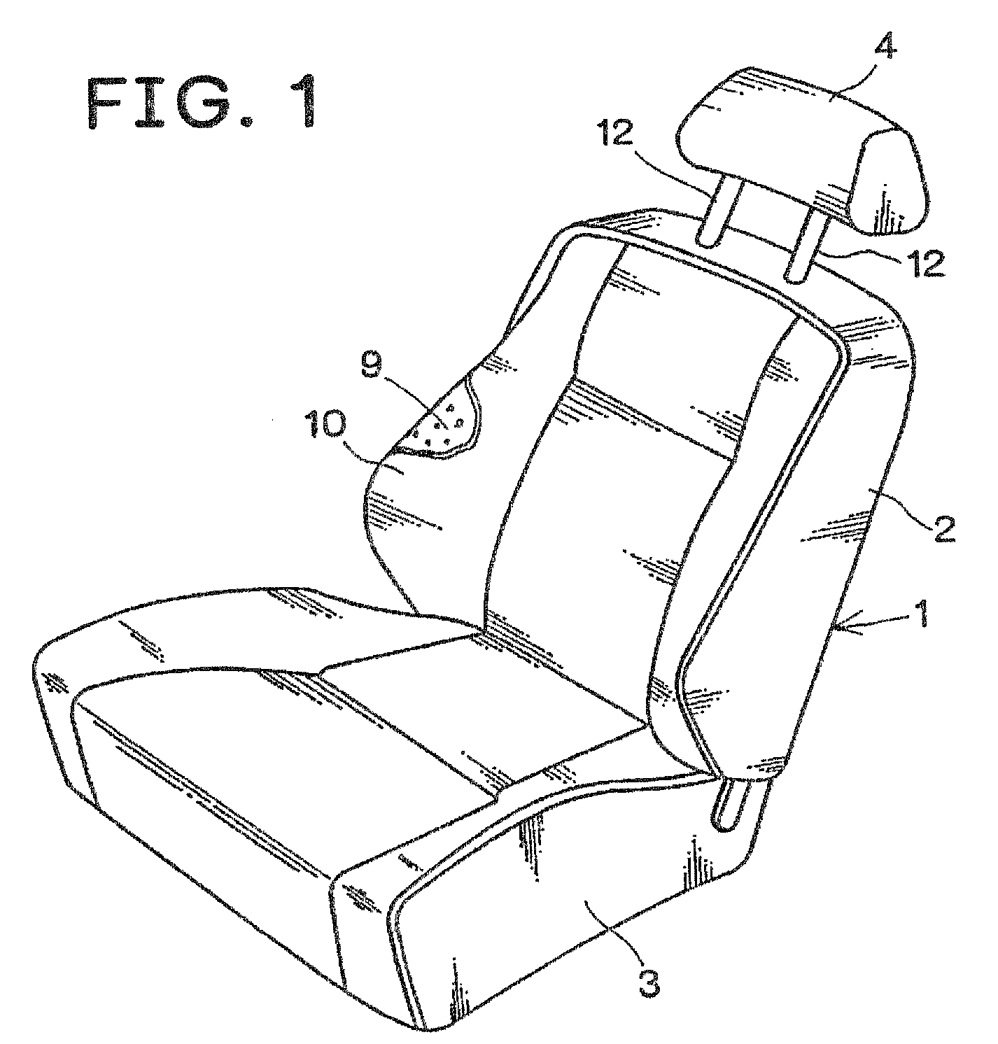
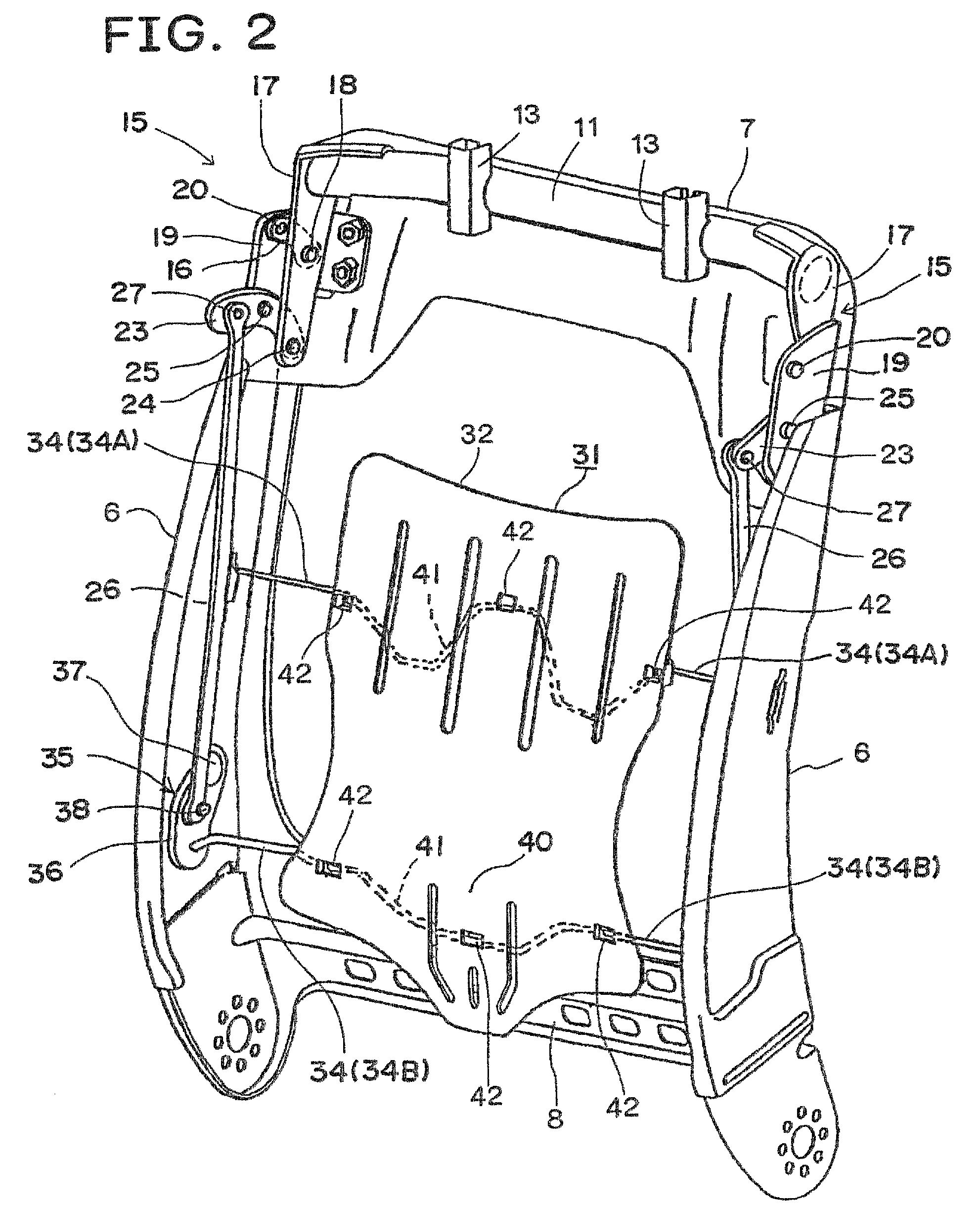
The present invention provides an active headrest mechanism that is free from the problems stated above. The invention uses a flexible cushion plate mounted on the seat spring to hold the seat cushion, which supports the seat occupant on a "plane" in a wide range. This results in a more stable and comfortable seating position for the occupant. The cushion plate and seat spring also act as a collision load detector, allowing for reliable detection of the collision load without impairing the comfort of the seat back. The invention reduces the number of parts of the active headrest mechanism and the weight of the seat.

Problems solved by technology

The conventional detector does not operate in cooperation with a member providing comfort of the seat back (for example, seat spring or seat cushion), but it rather acts to possibly deteriorate the comfort of the seat back.
In other words, if the seat cushion is sufficiently thick, a movable range of the detector is insufficient, so that the operation reliability of the active headrest mechanism is lost.

Method used


Image

  • Active headrest mechanism for vehicle seat
  • Active headrest mechanism for vehicle seat
  • Active headrest mechanism for vehicle seat

Examples


embodiment

Operation of Embodiment

[0032]Upon receiving the normal load from the seat occupant T, the cushion plate 31 moves rearward within the predetermined range of distance while being properly deformed and resisting the resilience of the seat spring 34. The plate 31 receives the normal load through the cushion 9 in its entirety, and the normal load is dispersed into the whole plate 31. Therefore, the back of the seat occupant T is kept in a good position.

[0033]When the vehicle seat 1 is moved forward relative to the seat occupant T by the rear-end collision, a collision load in excess of the normal load is applied to the cushion plate 31, so that the plate 31 greatly moves rearward beyond the predetermined range of distance. This movement rotates the turn arm 36 with the aid of the lower seat spring 34B counterclockwise from a position indicated by a dotted line to a position indicated by a solid line in FIG. 5, thereby to lower the coupling rod 26. In turn, the turn arms 23 of the upper l...


PUM


Abstract

A vehicle seat of the invention includes: a rectangular-shaped seat back frame (5) having a pair of side frames (6); a plurality of seat springs (34A, 34B) disposed between the side frames; a single plate-shaped flexible cushion plate (31) attached to the seat springs; a seat cushion (9) provided on the front side of the cushion plate; link mechanisms (15, 35) provided near the side frames; and a headrest (4) coupled to the link mechanisms (15). Both ends of the seat spring (34B) are coupled to the link mechanisms. When the seat spring (34B) is moved rearward, the headrest is moved forward. Both sides of each of the remaining seat springs (34A) are mounted to the side frames.

Description

TECHNICAL FIELD[0001]The present invention relates to an active headrest mechanism for a vehicle seat, and more particularly to improvement of a detection mechanism for a rear-end collision in the active headrest mechanism.BACKGROUND ART[0002]The conventional active headrest mechanism has a collision load detector provided in a seat back and a coupling mechanism for operatively coupling the detector and the headrest (Patent Documents 1 and 2).[0003]When a rear-end collision occurs and a seated person is moved rearward with respect to the seat back, the detector receives a collision load from the vehicle seat occupant and is moved rearward, and the rearward movement of the detector acts on the headrest through the coupling mechanism to move the headrest forward.[0004][Patent Document 1] Japanese Patent Application Laid-Open No. 2000-211410[0005][Patent Document 2] Japanese Patent Application Laid-Open No. 10-138814DISCLOSURE OF THE INVENTION[0006]The conventional detector does not op...

Claims


Application Information

Patent Timeline
Patent Type & Authority Patents(United States)
IPC IPC(8): B60N2/427B60R21/00
CPCB60N2/4885B60N2/4838B60N2/838B60N2/888
Inventor NIITSUMA, KENICHINEGISHI, HIROOKITANABE, JINICHIUNO, KOJITERAUCHI, TATSUYAMATSUMOTO, TOMOKISANO, KOJI
Owner TS TECH CO LTD
Learn More