
Image forming apparatus, component, component checking method, control program, and storage medium

a technology of image forming apparatus and components, applied in electrographic process apparatus, printing, instruments, etc., can solve the problems of difficult to design new cartridges to match all image forming apparatus, difficult to design ink ejection control and recovery devices for preventing, and difficult to achieve nozzles in a way that match new cartridges

Inactive Publication Date: 2010-06-08
CANON KK
View PDF7 Cites 2 Cited by
  • Summary
  • Abstract
  • Description
  • Claims
  • Application Information

AI Technical Summary

Benefits of technology

[0008]An object of this invention is to provide an image forming apparatus capable of correctly checking a compatibility between the image forming apparatus and a component that can be mounted on the apparatus, a component, a functional component checking method, a control program, and storage medium.
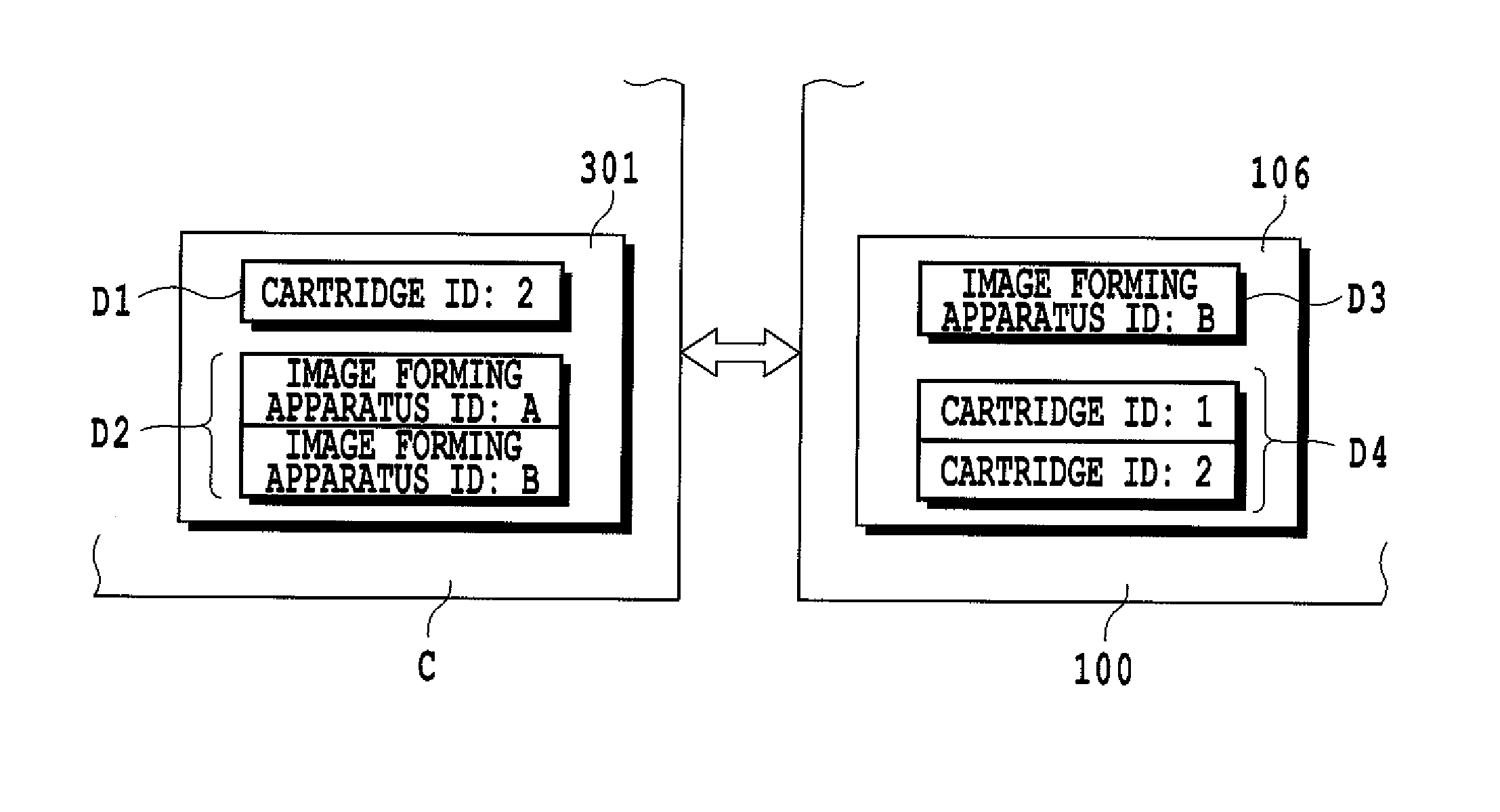
[0029]As described above, this invention compares the first and second information stored in the component with the third and fourth information stored in the image forming apparatus. This makes it possible to precisely check the compatibility between the image forming apparatus and the component that can be installed in the apparatus. Further, by putting the identification information of the image forming apparatus that were sold in the past in the second information stored in a component that is newly manufactured and marketed, the image forming apparatus capable of using the component can be set freely and correctly without having to modify the image forming apparatus at all.

Problems solved by technology

It is, however, often difficult to design new cartridges to match all image forming apparatus that were using old cartridges.
For example, if the image forming apparatus is an ink jet printer, designing an ink ejection control and a recovery device for preventing possible clogging of ink ejection nozzles in a way that match new cartridges is difficult to achieve.
Further, since the new cartridge needs to be able to be installed in the image forming apparatus that were sold in the past, new consumables cannot be changed in their shape from old ones.
However, with the method described in the Japanese Patent Application Laid-open No. 2000-246921, the image forming apparatus that were sold in the past cannot identify ID information of the new cartridge correctly.
The method disclosed in Japanese Patent Application Laid-open No. 2002-225307 that requires the use of a computer, however, cannot be applied to these image forming apparatus that do not require a computer.

Method used


Image

  • Image forming apparatus, component, component checking method, control program, and storage medium
  • Image forming apparatus, component, component checking method, control program, and storage medium
  • Image forming apparatus, component, component checking method, control program, and storage medium

Examples


first embodiment

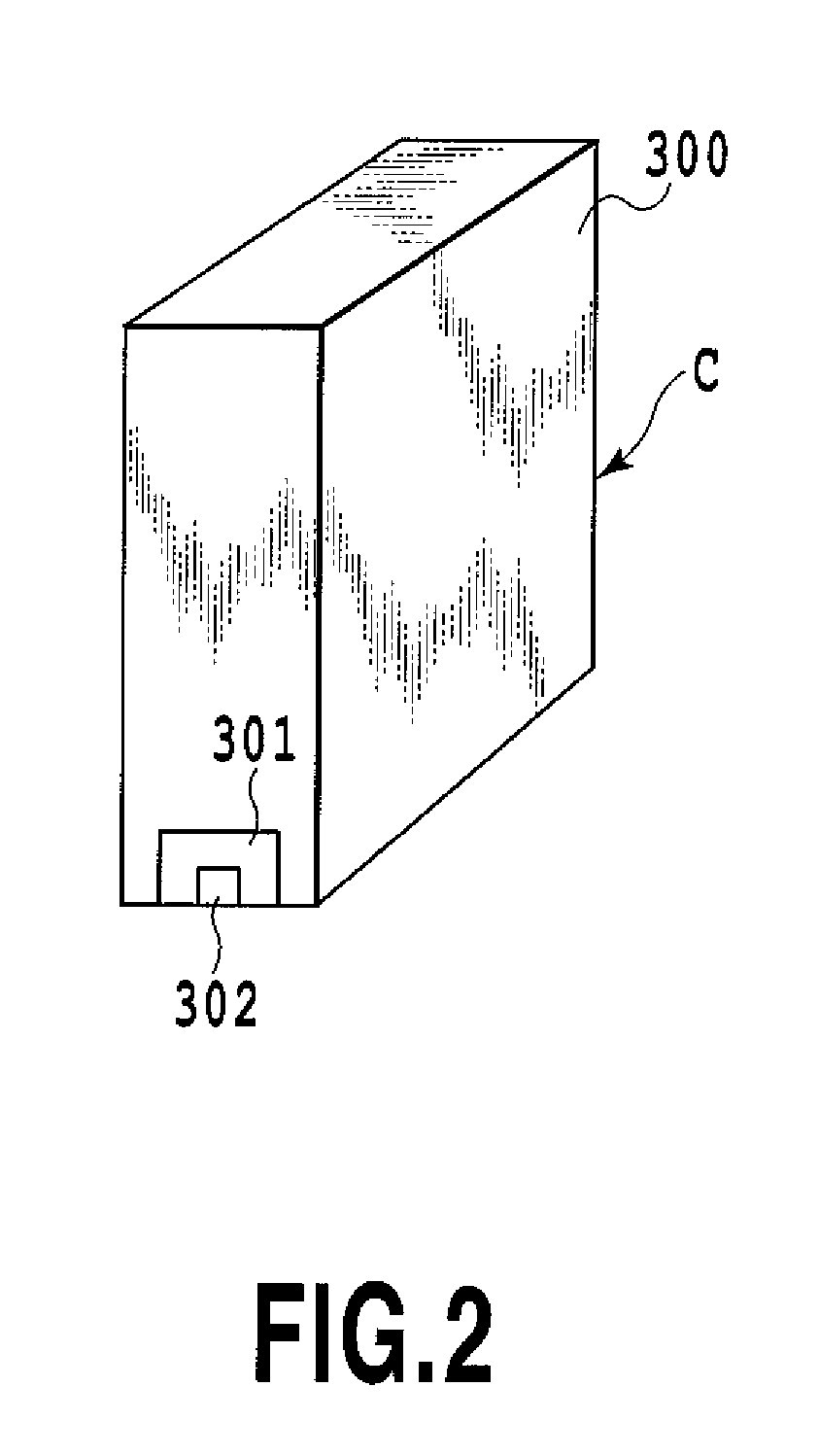
[0040]As a first embodiment of this invention, a case will be described in which a cartridge (ink cartridge) accommodating ink is mounted as a component on an image forming apparatus (printing apparatus) that forms an image using ink. It is noted, however, that this invention does not limit the number of cartridges mounted on the image forming apparatus to only one. The cartridge is not limited to only those ink cartridges containing ink but may be those accommodating a variety of kinds of consumables, such as print medium. The cartridge is only one form of the component and may be storage medium storing programs and data used on the image forming apparatus.

[0041]Among ink cartridges that may be mounted on the image forming apparatus, there is a 2-cartridge type that separately accommodates a black (K) ink and color inks such as cyan (C), magenta (M) and yellow (Y) inks. An individual type ink cartridge is also available which individually and separately accommodates all C, M, Y and...

second embodiment

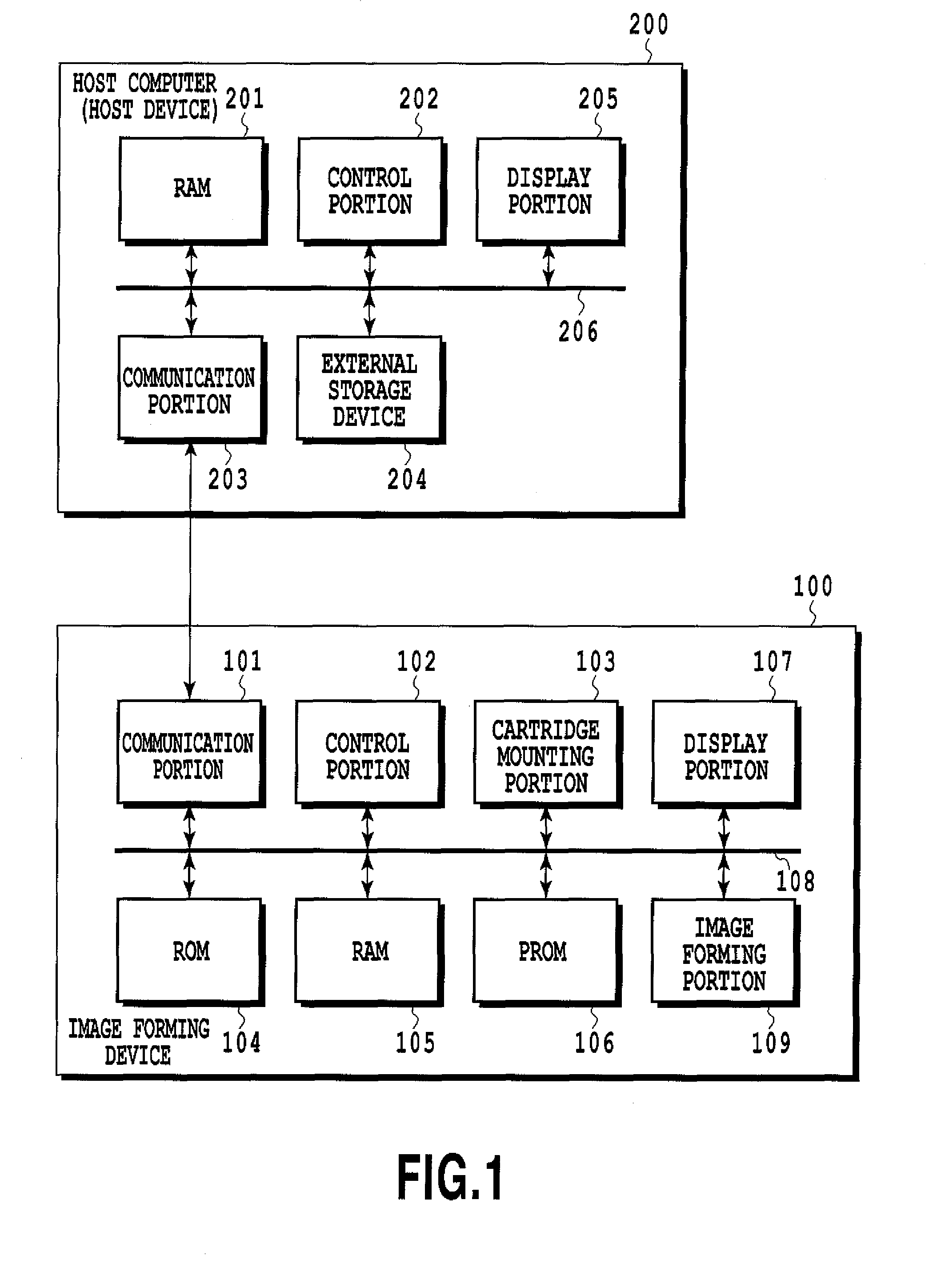
[0063]The image forming apparatus of the first embodiment is so constructed as to be able to check if a variety of kinds of cartridges including new cartridges can be used or not. Further, without changing such a basic construction, it is possible to prompt the user to update software (driver) that instructs the image forming apparatus to perform the image forming operation. Cartridges having IDs different from those of conventionally used cartridges are often those cartridges (such as ink cartridges) accommodating consumables with different characteristics from the conventional ones. Such a case mostly requires a printer driver (software) different from that of the conventional cartridge. Normally, the printer driver is installed in the host computer 200 and is used to control the image forming apparatus 100.

[0064]FIG. 5 is a flow chart showing an example of cartridge identification processing in the second embodiment of this invention.

[0065]Steps from S600 to S609 are the same as ...


PUM


Abstract

With this invention, compatibility between an image forming apparatus and a component mounted on the image forming apparatus is precisely checked. A cartridge, as the component, stores its ID (first information) and an ID (second information) of the image forming apparatus that can use the cartridge. The image forming apparatus stores its ID (third information) and an ID (fourth information) of the cartridge that can be used in the image forming apparatus. Then, when the fourth information includes the first information or the second information includes the third information, it is decided that the cartridge mounted in the image forming apparatus can be used. When the fourth information does not include the first information and the second information does not include the third information, it is decided that the cartridge mounted in the image forming apparatus cannot be used.

Description

BACKGROUND OF THE INVENTION[0001]1. Field of the Invention[0002]The present invention relates to an image forming apparatus and a component used on the image forming apparatus. The present invention also relates to a component checking method to decide whether the component is available for use with the image forming apparatus, a control program to cause a computer to execute the checking method, and storage medium to store the control program.[0003]2. Description of the Related Art[0004]Generally, image forming apparatus (printing apparatus), such as ink jet printers, have replaceably mounted on their bodies cartridge type components that accommodate consumables, such as ink and print medium (also referred to simply as “cartridges”). Such cartridges are available on the market separate from the image forming apparatus body. Since new products of the image forming apparatus are introduced into the market in a short cycle of every year or half, few improvements on their performances ...

Claims


Application Information

Patent Timeline
Patent Type & Authority Patents(United States)
IPC IPC(8): B41J29/393
CPCB41J2/17526B41J2/17546G03G15/0863G03G21/1892G03G2215/0697G03G2221/1823
Inventor SUGIURA, HIROAKI
Owner CANON KK
Learn More