Paper cutting device and printer

a paper cutting device and printer technology, applied in printing, stock shearing machines, manufacturing tools, etc., can solve the problems of limited freedom of positioning a scissor-type unavoidable increase in and limit the location of the paper cutting device in the printer. to achieve the effect of increasing the size of the printer

Inactive Publication Date: 2010-06-08
SEIKO EPSON CORP
View PDF25 Cites 17 Cited by
  • Summary
  • Abstract
  • Description
  • Claims
  • Application Information

AI Technical Summary

Benefits of technology

[0007]The fixed blade and movable blade are both substantially flat knives. A scissor-type paper cutting device cuts by driving these knives to intersect while overlapping through the thickness of the blades like regular scissors. As a result, a scissor-type paper cutting device must have enough space to house both of these blades in either the vertical or the longitudinal direction of the printer, that is, the direction in which the fixed blade and movable blade oppose each other. Space is also needed for the movable blade to pivot in either the vertical or the longitudinal direction of the printer. This space must be provided in either the vertical or longitudinal direction of the printer, and therefore limits where the paper cutting device can be located in the printer. As a result, there is limited freedom positioning a scissor-type paper cutting device in the printer, and increasing the size of the printer is unavoidable.
[0008]More particularly, if the paper exit faces the front or the back at the top of the printer, the printed paper will be discharged from the front or the back. The fixed blade and movable blade must therefore be disposed in opposition vertically to the paper exit in order to cut the paper, and incorporating this type of paper cutting device increases the height of the printer.

Problems solved by technology

This space must be provided in either the vertical or longitudinal direction of the printer, and therefore limits where the paper cutting device can be located in the printer.
As a result, there is limited freedom positioning a scissor-type paper cutting device in the printer, and increasing the size of the printer is unavoidable.
Satisfying these needs is not possible by using of the prior art, however.

Method used


Image

  • Paper cutting device and printer
  • Paper cutting device and printer
  • Paper cutting device and printer

Examples


Embodiment Construction

[0052]A preferred embodiment of the present invention is described below with reference to the accompanying figures.

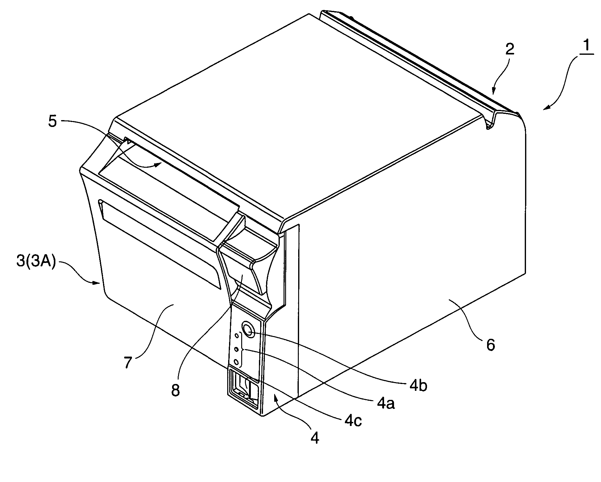
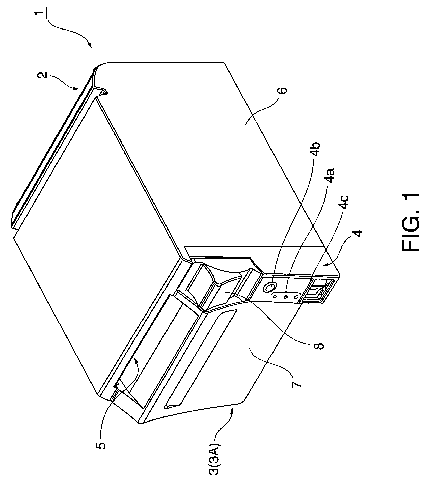
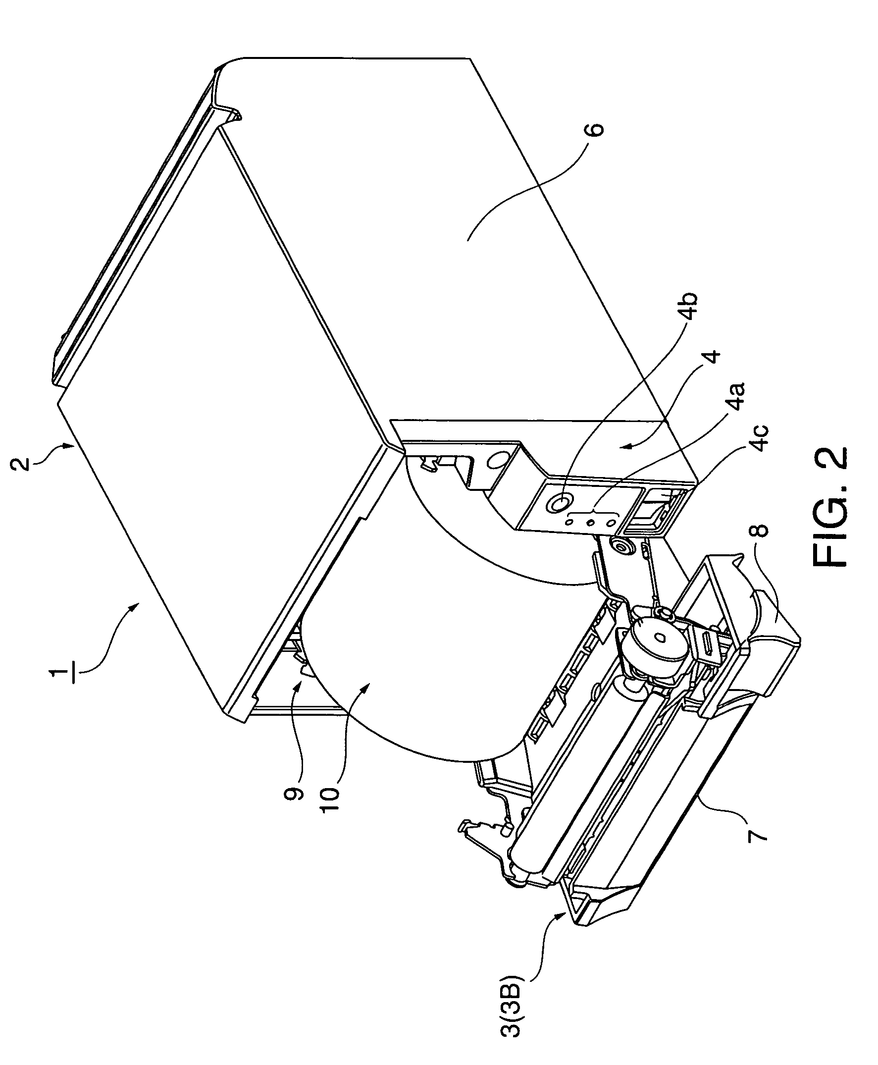
[0053]FIG. 1 is an oblique external view of a thermal printer according to the present invention, and FIG. 2 an is oblique view showing the printer when the operable cover unit is open.

[0054]A thermal printer 1 according to this embodiment of the invention has a printer chassis 2 with an operable cover unit 3 attached at the front. An operating panel unit 4 is disposed to a front corner of the printer chassis 2. A paper exit 5 extending widthwise to the printer is formed at the top part of the operable cover unit 3 at the front of the printer.

[0055]The printer chassis 2 is covered by a box-like printer case 6 that has a long depth front to back and is open at the front and bottom sides. An operable cover case 7 that defines the printer front is attached at the front of the operable cover unit 3. Operating an operating lever 8 located at the operating panel unit 4 relea...


PUM

PropertyMeasurementUnit
forceaaaaaaaaaa
angleaaaaaaaaaa
resistanceaaaaaaaaaa

Abstract

A paper cutting device comprising a fixed blade, a movable blade, a movable blade drive mechanism for moving the movable blade, wherein the movable blade and the fixed blade are disposed in substantially perpendicular positions.

Description

BACKGROUND OF THE INVENTION[0001]1. Field of Technology[0002]The present invention relates to a paper cutting device for cutting printed recording paper, and to a printer in which this paper cutting device is incorporated.[0003]2. Description of Related Art[0004]Printers that print to a long tape of recording paper wound into a roll on a core (that is, roll paper) commonly have a paper cutting device disposed near the paper exit for cutting the paper to a certain length after the paper is printed. One type of such paper cutting device is a scissors-like device comprising a fixed blade and a movable blade. Japanese Unexamined Patent Appl. Pub. H8-309689 teaches a scissor-type paper cutting device, and Japanese Unexamined Patent Appl. Pub. H9-254474 teaches a printer comprising a scissor-type paper cutting device.[0005]The paper cutting device of the printer taught in Japanese Unexamined Patent Appl. Pub. H9-254474 has the fixed blade mounted on an operable cover that opens and closes...

Claims


Application Information

Patent Timeline
Patent Type & Authority Patents(United States)
IPC IPC(8): B41J11/00B41J11/70
CPCB26D1/085B41J15/042B41J11/70B26D5/14B26D2007/2685B26D2001/0066Y10T83/4847Y10T83/8837Y10T83/8843
Inventor SHIROTORI, MOTOYOSHIMAEKAWA, HIRONORI
Owner SEIKO EPSON CORP
Why Eureka
Try Eureka