Automated motor vehicle transmission and method of operating the same

a technology of automatic transmission and motor vehicle, which is applied in the direction of mechanical equipment, transportation and packaging, etc., can solve the problems of difficult configuration of possible transmission ratios and the peripheral conditions of dividing power outputs between power branches, and achieve the effects of improving the method of operating the transmission, reducing losses, shifting times and/or shifting processes

Inactive Publication Date: 2010-06-08
DAIMLER AG
View PDF17 Cites 2 Cited by
  • Summary
  • Abstract
  • Description
  • Claims
  • Application Information

AI Technical Summary

Benefits of technology

[0012]According to the invention, a first component transmission of a reduction gearing design is used. As a result, the advantages of transmissions of a reduction gearing design, which are known per se, can be utilized, in particular the advantages of a free configuration of the transmission ratios, a design with standard elements, a high possible number of gears of a reduction gearing design, the possibility of multiplying the number of possible gears by using a plurality of input-end constants, the possibilities of using split groups and / or range groups as well as the compact design of reduction gearing units.
[0076]This configuration thus constitutes a compromise in terms of minimizing the expenditure on synchronization and the synchronization time, on the one hand, and the power losses in the direct gear, on the other hand. The probable residence time can be determined in particular by means of a predictor method which has already been previously mentioned and / or, for example, by means of empirical values which have been acquired on the basis of the previous driving behavior or GPS data and road information.

Problems solved by technology

However, the abovementioned power branches can be combined only if the two countershafts rotate at the same rotational speed, which makes the periphery conditions for dividing the power outputs between the power branches and the configuration of the possible transmission ratios more difficult.

Method used


Image

  • Automated motor vehicle transmission and method of operating the same
  • Automated motor vehicle transmission and method of operating the same
  • Automated motor vehicle transmission and method of operating the same

Examples


Embodiment Construction

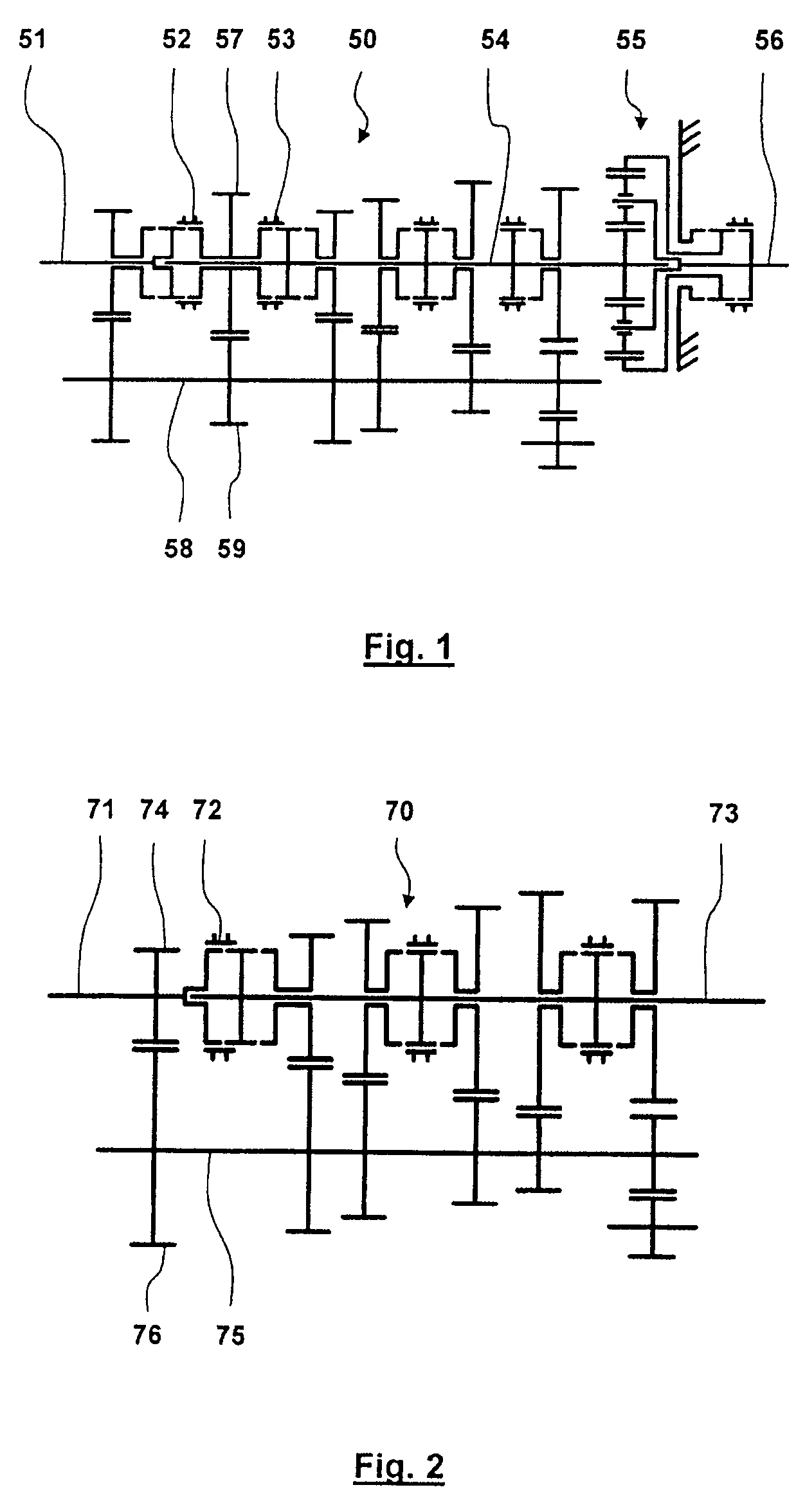
[0098]The transmission 50 illustrated in FIG. 1 is a conventional group transmission with a component transmission of a reduction gearing design and with a direct gear. In the activated direct gear illustrated in FIG. 1, the drive torque is transmitted from an input shaft 51 via a gear shifting element 52 and a gear shifting element 53 which is connected to the gear shifting element 52 so as to rotate with it, to a main shaft 54 which is connected to the output shaft 56 via the planetary gear set 55 which rotates in the direct gear in the block. A gearwheel 57, which intermeshes with a gearwheel 59 which is connected to the countershaft 58 so as to rotate with it is connected to the gear shifting elements 52, 53 so as to rotate with them, with the result that in the direct gear the countershaft 58 is also rotated by the input shaft 51. According to FIG. 1, the gear shifting element 52 does not transmit any drive torque in the neutral position, while the drive movement is transmitted...


PUM


Abstract

In a transmission for a motor vehicle of a reduction gearing design with power branching including a main shaft and a counter shaft, a first component transmission and a planetary gear unit, power is branched to the countershaft by the first component transmission in certain gears and recombined via the planetary gear unit and a direct power transmission path is provided wherein the countershaft is decoupled selectively by means of a control device.

Description

[0001]This is a Continuation-In-Part Application of pending International Patent Application PCT / EP2005 / 006449 filed Jun. 16, 2005 and claiming the priority of German Patent Applications 10 2004 046 074.4, 10 2004 951 453.6 and 10 2004 054 852.8 filed Sep. 23, 2004, Oct. 22, 2004 and Nov. 13, 2004, respectively.BACKGROUND OF THE INVENTION[0002]The invention relates to an automated transmission of a reduction gearing design having a plurality of discrete transmission stages and power branches for a motor vehicle and to a method of operating such a transmission.[0003]U.S. Pat. No. 5,381,703 and DE 100 51 354 A1 disclose transmissions of a reduction gearing design, in which, in direct gear, an input shaft of the transmission is connected to an output shaft of the transmission so as to rotate with it and without intermediate intermeshing gearwheels. In such a direct gear the countershaft is decoupled from the input shaft and the output shaft gear shifting elements are shifted into a neu...

Claims


Application Information

Patent Timeline
Patent Type & Authority Patents(United States)
IPC IPC(8): F16H37/04
CPCF16H37/0833F16H61/70F16H37/046F16H2200/0065Y10T74/19219F16H2306/48F16H2312/00Y10T74/19242F16H2306/18F16H37/08
Inventor GITT, CARSTENSCHNITZER, DETLEF
Owner DAIMLER AG
Why Eureka
Try Eureka