A miniature high-frequency heating power supply for quenching

A high-frequency heating and high-frequency technology, which is applied in the direction of quenching device, energy efficiency improvement, process efficiency improvement, etc., can solve the problems of bulky, large volume, low efficiency, etc., and achieve the reduction of overall occupied space, saving investment cost, The effect of saving factory space

Active Publication Date: 2016-07-13
INDUCTOTHERM GROUP CHINA +1
View PDF6 Cites 0 Cited by
  • Summary
  • Abstract
  • Description
  • Claims
  • Application Information

AI Technical Summary

Problems solved by technology

[0004] 1) The high-frequency heat treatment quenching power supply of IGBT components as the main components of the inverter can only meet the power, but cannot provide high frequency. For the surface heat treatment of workpieces with large areas and shallow quenching depth requirements, the power frequency requirements are higher. , it cannot satisfy;
[0005] 2) Electron tube high-frequency power supply can only provide higher frequency, which cannot meet the requirements of power and volume. Although the heating frequency can meet the surface heat treatment of workpieces with shallow quenching depth requirements, its efficiency is too low and the volume is too large. It is conducive to the heat treatment of high-precision components, and the old-fashioned electronic tubes generate a lot of heat during operation and have low electrical efficiency. Such products have been gradually replaced by thyristor or IGBT components since the 1990s
[0006] 3) Large volume, when dealing with the surface quenching of large parts, when large power and high frequency are required, when the existing MOSFET high-frequency power supply exceeds 100KW, most of them adopt a separate structure, that is, the DC system and the inverter The oscillation system is connected by cables in the middle, which makes the volume larger, which is not a small defect for quenching equipment

Method used


Image

  • A miniature high-frequency heating power supply for quenching
  • A miniature high-frequency heating power supply for quenching
  • A miniature high-frequency heating power supply for quenching

Examples


Embodiment Construction

[0032] The present invention will be further described below in conjunction with accompanying drawing.

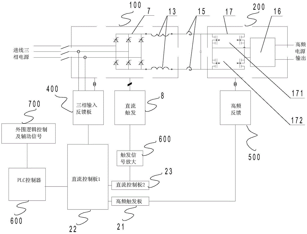
[0033] see figure 1 with figure 2 , the miniature high-frequency heating power supply for quenching of the present invention includes a rectification and voltage regulation system 100, a high-frequency resonance generation system 200 and a control system.

[0034] The rectification and voltage regulation system 100 includes a three-phase full-bridge rectifier bridge 7, two smoothing reactors 13, positive and negative balance coils 15 and a filter capacitor bank 27; , the negative output end in series; the positive and negative balance coils 15 are connected in series with the other ends of the two smoothing reactors 13 in one-to-one correspondence;

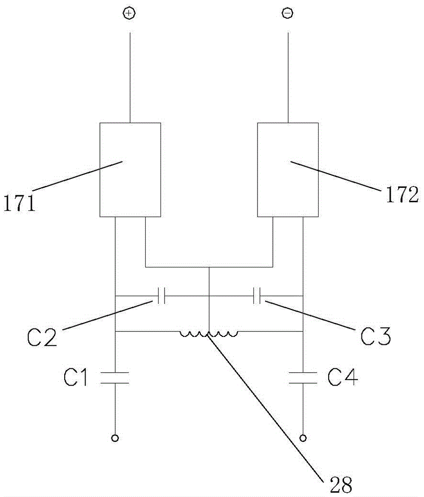
[0035] The high-frequency resonance generating system 200 includes a high-frequency power component 17 and a resonant capacitor tank 16; wherein, the high-frequency power component includes four MOSFET power devices, and two...


PUM


Abstract

The invention discloses a miniature high-frequency heating power source for quenching. The miniature high-frequency heating power source for quenching is low in operation cost and high in efficiency. The miniature high-frequency heating power source for quenching comprises a rectifying voltage-regulating system, a high-frequency resonance generating system and a control system. The rectifying voltage-regulating system comprises a rectifier bridge, two smoothing reactors, a positive electrode and negative electrode balance coil and a filter capacitor component. The high-frequency resonance generating system comprises a high-frequency power assembly and a resonance capacitor tank circuit. The high-frequency power assembly comprises four power devices, wherein two of the power devices are connected in parallel to form the positive electrode, the other two power devices are connected in parallel to form the negative electrode, and then the four power devices are connected to the other end of the positive electrode and negative electrode balance coil in parallel. The resonance capacitor tank circuit comprises four capacitors and a short-circuit coil, wherein the capacitor C2 and the capacitor C3 are connected in series and then connected with the positive electrode and the negative electrode of the high-frequency power assembly in parallel respectively, and the capacitor C1 and the capacitor C4 are connected with the positive electrode and the negative electrode of the high-frequency power assembly in series in a one-to-one correspondence mode. The short-circuit coil is connected with the positive electrode and the negative electrode of the high-frequency power assembly in parallel and the midpoint of the short-circuit coil is connected with a connection node between the capacitor C2 and the capacitor C3.

Description

technical field [0001] The invention relates to a heating power supply for quenching, in particular to a miniature high-frequency heating power supply for quenching. Background technique [0002] At present, the heat treatment industry has been booming in many fields in China, mainly because with the continuous development of my country's machinery manufacturing industry, my country's quality requirements for aerospace, military supplies, automobiles and some high-end mechanical parts continue to increase, especially for some The requirements for surface heat treatment are getting higher and higher, and the demand for quenching heat treatment equipment has also continuously put forward various requirements. As far as the current domestic situation is concerned, high-frequency quenching equipment is mainly divided into two categories: one is the old-fashioned high-frequency equipment using vacuum tubes, and the other is the new high-frequency equipment using integrated circuit...

Claims


Application Information

Patent Timeline
Patent Type & Authority Patents(China)
IPC IPC(8): H02M5/458C21D1/62C21D1/10
CPCY02P10/25
Inventor 迈克·耐伦张健
Owner INDUCTOTHERM GROUP CHINA
Why Eureka
Try Eureka