Moving body

A mobile body and sensor technology, applied in the field of mobile bodies, to achieve the effect of free configuration

Pending Publication Date: 2019-10-08
SHARP KK
View PDF7 Cites 0 Cited by
  • Summary
  • Abstract
  • Description
  • Claims
  • Application Information

AI Technical Summary

Problems solved by technology

However, this method has the following problems: the installation height of the obstacle sensor is limited to the height of the top surface of the traveling device, so that a height lower than this cannot be set within the detection range

Method used


Image

  • Moving body
  • Moving body
  • Moving body

Examples


no. 1 approach

[0051] Hereinafter, the moving body of the first embodiment of the present invention will be described with reference to the drawings.

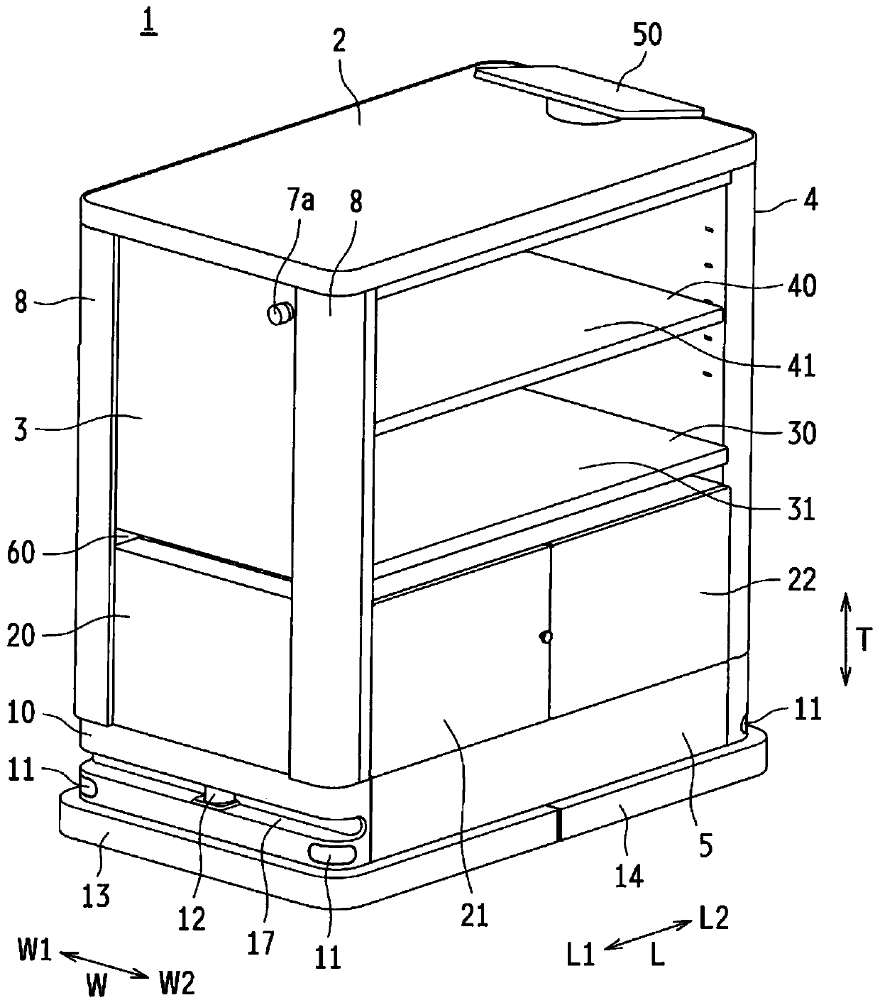
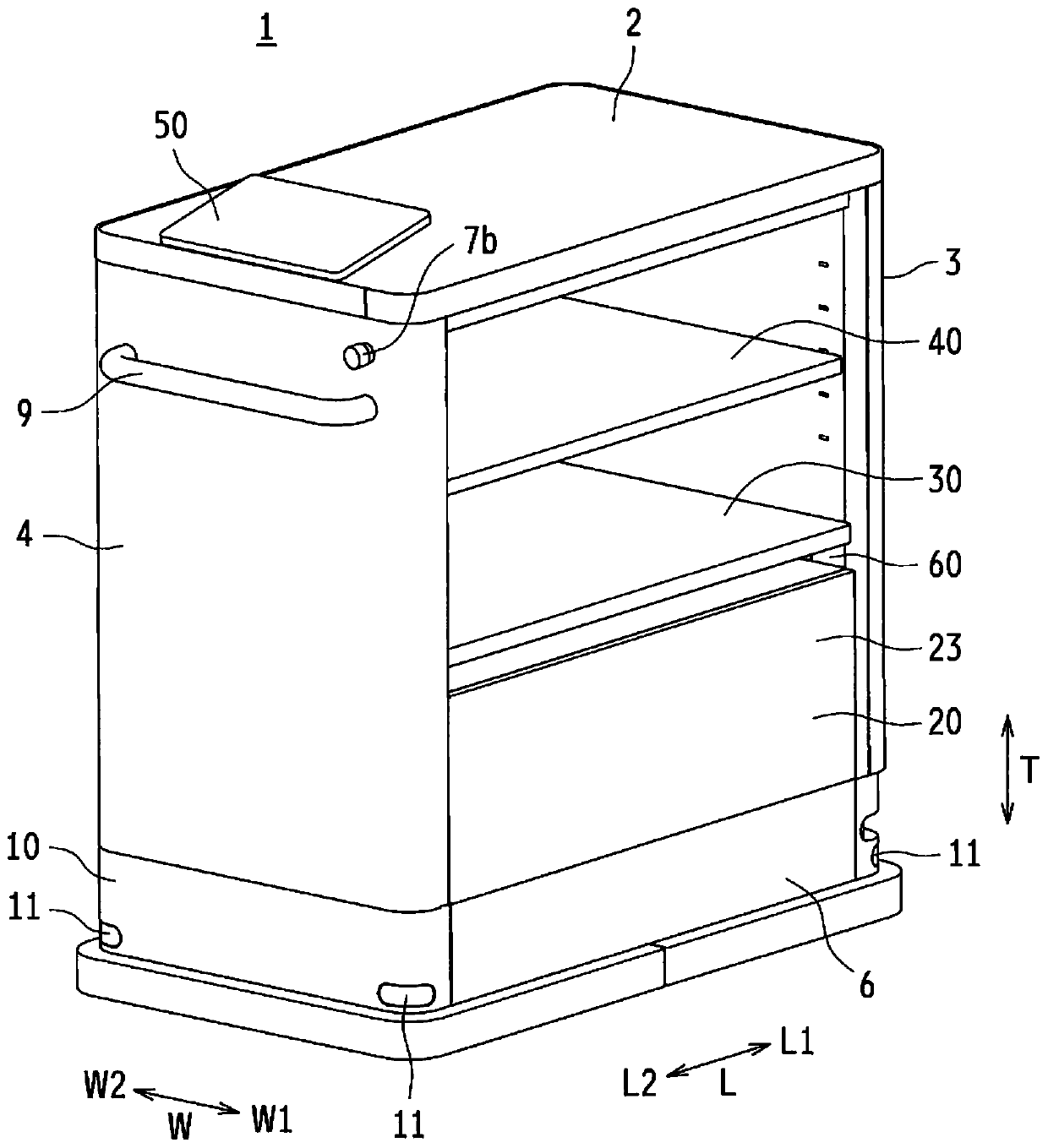
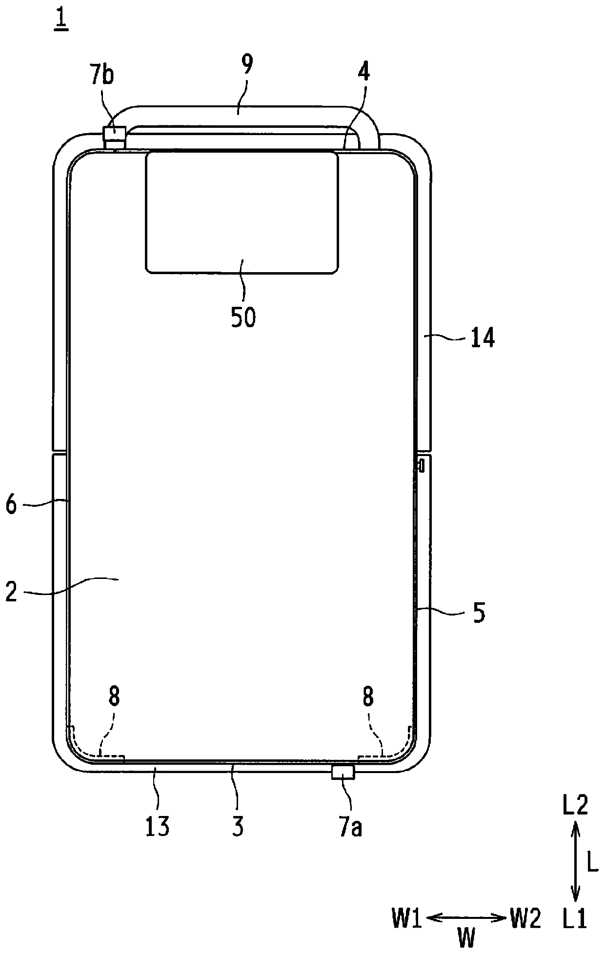
[0052] figure 1 In order to show the appearance perspective view of the state of the mobile body of the first embodiment of the present invention viewed diagonally from the front left, figure 2 Obliquely viewed from the rear right for the display figure 1 The external perspective view of the state of the moving body shown, Figure 3A for figure 1 A schematic plan view of the moving body shown, Figure 3B View from the front for display figure 1 A schematic side view of the state of the moving body shown, Figure 3C View from the rear for display figure 1 A schematic side view of the state of the moving body shown, Figure 3D View from the left for display figure 1 A schematic side view of the state of the moving body shown, Figure 3E View from the right for display figure 1 A schematic side view of the state of the moving body shown.

[0053] The ...

no. 2 approach

[0128] Next, the moving body 1 of the second embodiment of the present invention will be described with reference to the drawings. In addition, components having the same functions as those of the first embodiment are given the same reference numerals, and their description is omitted.

[0129] Figure 10A To illustrate a side view showing a state in which each part of the mobile body of the second embodiment of the present invention is divided, Figure 10B For display will Figure 10A An explanatory side view of the state of the combined parts of the moving body shown.

[0130] Figure 10A The drive housing 10 and the power housing 20 corresponding to the lower structure KZa are shown in a state where the front side wall portion 100, the rear side wall portion 110, the upper side wall portion 120, and the longitudinal bumper 8 are removed. In the second embodiment, the structures of the front side wall portion 100, the rear side wall portion 110, and the longitudinal bumper 8 are ...

no. 3 approach

[0134] Next, the moving body 1 of the third embodiment of the present invention will be described with reference to the drawings. In addition, components having the same functions as those of the first embodiment and the second embodiment are given the same reference numerals, and their description is omitted.

[0135] Figure 11A To illustrate a side view showing a state in which each part of the moving body of the third embodiment of the present invention is divided, Figure 11B For display will Figure 11A An explanatory side view of the state of the combined parts of the moving body shown.

[0136] Figure 11A It shows that the drive housing 10, the power housing 20, the first upper housing 141, the second upper housing 142, the third upper housing 143, the longitudinal bumper 8 and the like are separated for the moving body 1 of the third embodiment After the state. The third embodiment has a structure in which a plurality of layers (housings) are stacked, like the first embo...


PUM


Abstract

The invention provides a moving body, which can take both the detection angle range and height setting freedom of an obstacle sensor into account. The moving body (1) includes lower structural bodies(a drive housing (10) and a power housing (20)), upper structural bodies (a first transporting housing (30) and a second transporting housing (40)) that are disposed above the lower structural bodies,a wide-area sensor (61) that detects an object in a vicinity of the wide-area sensor by applying light towards the vicinity of the wide-area sensor, and a sensor accommodating section (60) that is interposed between an upper surface of one of the lower structural bodies and a lower surface of one of the upper structural bodies. In the moving body, a side surface of the sensor accommodating section (60) is provided with an emission window portion (for example, a left opening portion (62b)) facing an outside, and the emission window portion allows the light applied from the wide-area sensor (61) to be emitted towards the outside.

Description

Technical field [0001] The invention relates to a mobile body in which an upper structure is arranged on a lower structure. Background technique [0002] In recent years, in order to increase the efficiency of work, the use of AGVs (Automatic Guided Vehicles) for conveying articles is increasing. Since this type of unmanned guided vehicle does not require human operation, it includes a structure for detecting obstacles on the way to avoid collisions with obstacles. Therefore, a method of providing a sensor that detects a position with respect to an obstacle based on the irradiated light has been proposed (for example, refer to Patent Document 1 and Patent Document 2). [0003] The autonomous mobile robot (traveling device) described in Patent Document 1 includes a distance measuring sensor that detects the distance to an object by irradiating laser light, and the distance measuring sensor is installed on the top surface of the autonomous mobile robot. [0004] The autonomous mobile...

Claims


Application Information

Patent Timeline
Patent Type & Authority Applications(China)
IPC IPC(8): G01S17/93G01S7/481G01S17/04G01S17/931
CPCG01S7/4817G01S17/931G05D1/0227G05D1/0238G05D2201/0216G01S17/04
Inventor 中浦正贵
Owner SHARP KK
Why Eureka
Try Eureka