Method and system for tracking the positioning and limiting the movement of mobile machinery and its appendages

a technology for mobile machinery and its appendages, applied in the direction of thinning machines, instruments, machine control, etc., can solve the problems of damage to the body, device or sensor located on the machine, and problems such as damage or destruction of the body, and the problem of problematic use of onboard sensors

Active Publication Date: 2010-06-08
WILDCAT TECH
View PDF29 Cites 55 Cited by
  • Summary
  • Abstract
  • Description
  • Claims
  • Application Information

AI Technical Summary

Benefits of technology

[0011]It is desirable to provide a method and system that is capable of tracking and limiting the movement of key points on the body and / or appendages of mobile machines. Moreover, it is particularly desirable to provide such a method and system that actively limit the machine from exceeding the predetermined limits of operation for the machinery; that display the equipment's location relative to a predetermined surface design; and that interact with the equipment in a way that would limit the equipment from damaging an object and / or structure.
[0013]Further, it is an object of one or more embodiments of this invention to provide such a method and / or system for tracking and limiting the movement of key points on a body and / or appendages of a mobile machine that can actively limit the machine from exceeding the predetermined limits of operations.
[0016]Further, it is an object of one or more embodiments of this invention to provide such a method and / or system for tracking and limiting the movement of key points on a body and / or appendages of a mobile machine that interacts with the equipment in a manner that would limit the equipment from damaging an object and / or structure.
[0019]Further, it is an object of one or more embodiments of this invention to provide such a method and / or system for tracking and limiting the movement of key points on a body and / or appendages of a mobile machine that will typically place the GPS units on the top of the body of the equipment, thereby avoiding damage to the GPS units when the equipment is in use.

Problems solved by technology

The use of onboard sensors has been proven to be problematic, in that in many circumstances devices or sensors, which are located on the machines, body are destroyed or damaged during operation of the machine.

Method used


Image

  • Method and system for tracking the positioning and limiting the movement of mobile machinery and its appendages
  • Method and system for tracking the positioning and limiting the movement of mobile machinery and its appendages
  • Method and system for tracking the positioning and limiting the movement of mobile machinery and its appendages

Examples


Embodiment Construction

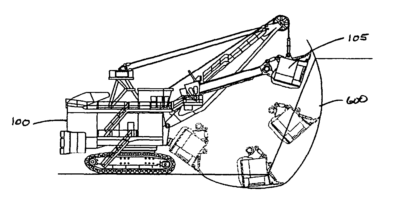
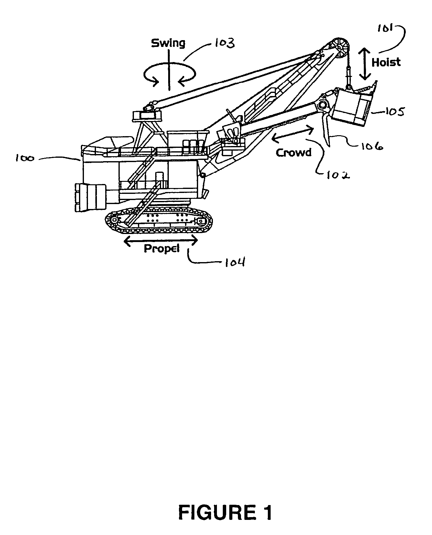
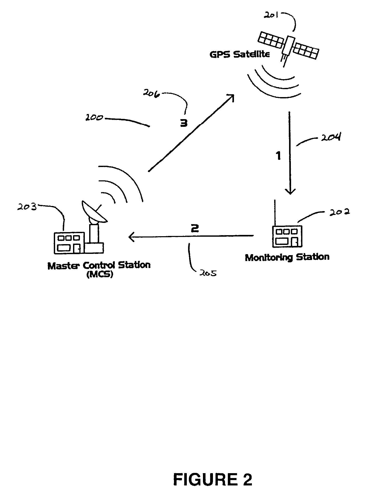
[0085]This invention is a method and system of tracking and limiting the movement of key points on the body and / or appendages of mobile machines, such as construction equipment and the like. The movement of these key points is tracked in an external coordinate system through the use of a minimum of one, or more preferably three or more location points and information supplied by the joint position monitors on the machine. The movement of the key points is then limited by comparing the current and / or predicted future location of the key points relative to three dimensional boundary data supplied by the end user.

[0086]This invention can be used and adapted for use with a wide variety of applications, including, but not necessarily limited to, mining and excavating, construction, hauling, lifting, loading, scraping, and other digging or drilling. The use of this invention in these applications can enable the final result of the work to conform to the initial design and to protect the m...


PUM


Abstract

A method and system for tracking and limiting the movement of key identified points on a movable machine, through the use of location devices positioned on the body or appendages of the machine, by comparing the sensed locations against a database of site information, and to restrict movement of the machine and / or its appendages if it has or is likely to pass through a defined boundary in the site information database.

Description

BACKGROUND OF THE INVENTION[0001]1. Field of the Invention[0002]This invention relates to techniques and devices for locating, tracking, positioning and limiting the movement of mobile machines and / or mobile appendages of machines. More specifically, this invention relates to the tracking and control of the positions of such machines that makes use of a computer system programmed to receive positional information and user specified three dimensional boundary information and then to limit the movement of the machine within the established boundaries.[0003]2. Description of Related Art[0004]A variety of devices and techniques for position tracking and control are well known in the field. These include the use of one or two location points and then supplementing this data with information from onboard sensors or movement algorithms. The use of onboard sensors has been proven to be problematic, in that in many circumstances devices or sensors, which are located on the machines, body are...

Claims


Application Information

Patent Timeline
Patent Type & Authority Patents(United States)
IPC IPC(8): E02F5/00
CPCE02F3/437G05D1/0278E02F9/2033G05D2201/0202
Inventor PETERSON, BRANDON J.NELSON, MICHAEL G.HUSTRULID, WILLIAM A.
Owner WILDCAT TECH
Why Eureka
Try Eureka