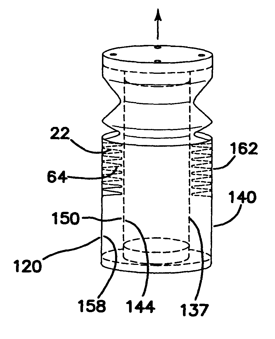
[0013]One embodiment of the present invention provides a rigidizable fluid and a container for the fluid. The container or containment member has at least one outer wall forming a closed vessel. The containment member further includes at least one opening and at least one exhaust port. The rigidizable fluid is injected, potentially though an injection port, or poured into the containment member through an opening. As the rigidizable fluid becomes rigid, it may release gases creating a pressure barrier. The pressure barrier may prevent the rigidizable fluid from advancing throughout the structure. In order to address this problem, excess pressure in the containment member can be exhausted through at least one exhaust port. If there is more than one outer wall, the innermost wall forms the containment member and the outermost wall may be a protective layer. The outermost wall may be selected to protect the structure against puncture from debris, rocks, meteors and the like, or from harmful radiation. The outer wall thickness may be selected for such properties as stiffness and strength or other desirable characteristics.
[0014]In an alternative embodiment, the structure further includes an inflatable bladder. The bladder is attached to the containment member and has at least one pressurizing port. The bladder can be inflated through the pressurizing port. Inflation of the bladder member also erects the containment member and gives the structure its shape prior to rigidization. The bladder member may be inflated with any gas or liquid. In the case of a biosphere, such as a habitat, the bladder provides a space that can support living organisms.
[0015]Another embodiment of the present invention provides a method for erecting and rigidizing a structure having an inflatable bladder attached to a containment member. The containment member includes at least one inner wall and at least one outer wall. First, the bladder is inflated to erect the structure. Then rigidizable fluid is introduced uniformly into the containment member between the inner wall and the outer wall by pouring or injection. The rigidizable fluid advances throughout the containment member and may release gas as it cures. The released gas is vented from the containment member to prevent the released gas from impeding the uniform distribution of injected rigidizable fluid.
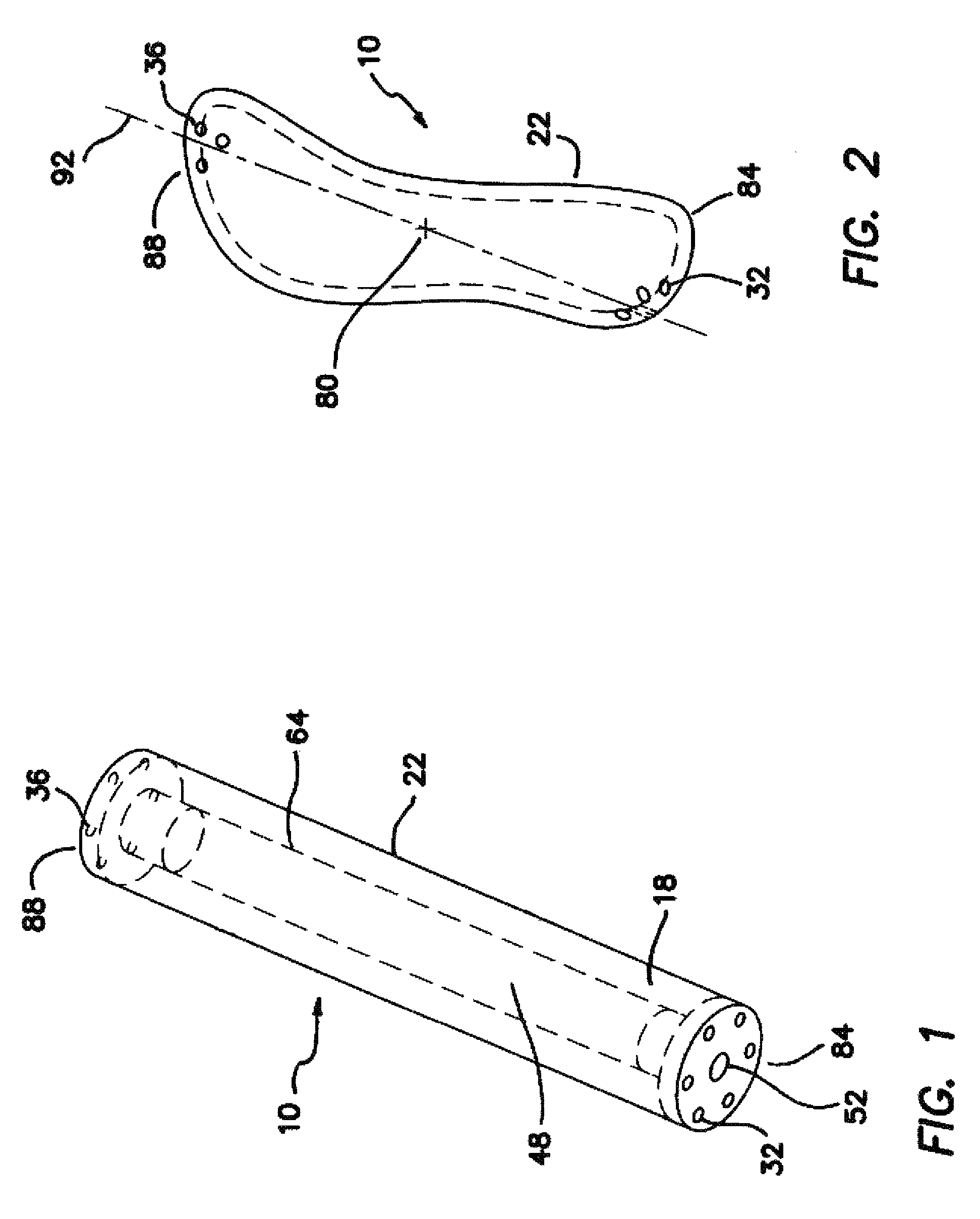
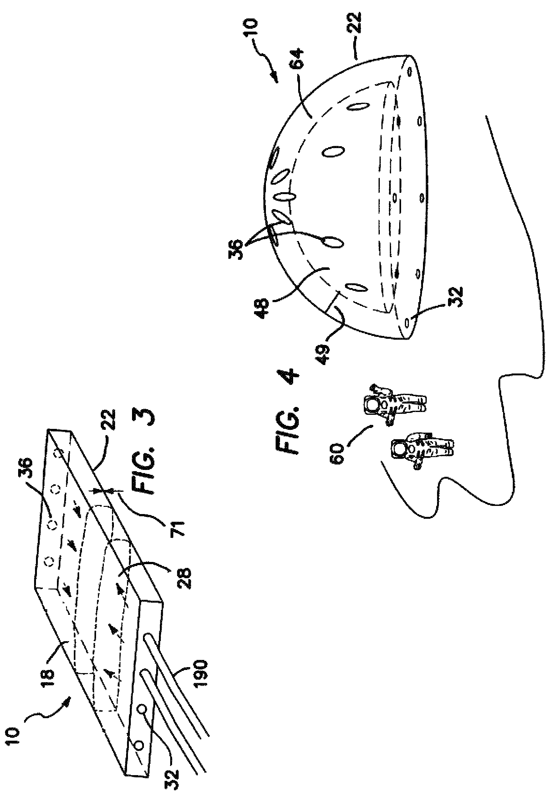
[0017]In another embodiment, the present invention provides a method for fabricating a tubular wall as follows: A tubular mold with a predetermined cross-section, a predetermined perimeter, and a predetermined length is selected. A section of flexible material with a predetermined length, and a width greater than the predetermined perimeter is also selected. It should be noted that a length shorter than the tubular mold may be selected, and such reduced length would facilitate ease of work. The width of flexible material is wrapped around the tubular mold and the two ends of the width are secured together forming a seam. The tubular mold is removed leaving a tubular wall having a first end and a second end. In another variant of the method, the tubular mold selected is a section of PVC pipe. In another embodiment, the present invention includes a plurality of rigidizable fluid containment areas and a network of transfer hoses, wherein the structure takes the form of a useful article selected from the group comprising: an enclosed storage structure including at least one movable door. The structure may be an enclosed dwelling structure including at least one door and at least one window, a support for equipment including a base and at least one component not in the plane of the base, and / or an open topped fluid container. Additional forms include a truss structure consisting of numerous tubular inflatable and rigidizable members, or alternatively the arrangement comprising a toroidal structure and tubular support structures, wherein the toroid can support a Fresnel lens, parabolic reflector or lens, or other components, and a framework for supporting advertising displays, aircraft wings and spacecraft appendages, wherein appendages may include solar panels.

