Guided rotary file

a rotary file and guide technology, applied in the field of machine tooling, can solve the problems of inability to program a specific toolpath to remove only the burr, inconsistencies in the size and shape of finished features, and the inability to remove the burr without removing the parent material

Inactive Publication Date: 2010-06-15
GENERAL ELECTRIC CO
View PDF13 Cites 8 Cited by
  • Summary
  • Abstract
  • Description
  • Claims
  • Application Information

AI Technical Summary

Problems solved by technology

This leads to inconsistencies in the finished feature size and shape.
The difficulty with automating these processes is removing the burr without removing parent material.
The burr size varies from part to part and the location of the feature can also vary making it impossible to program a specific toolpath to remove only the burr.
Unfortunately this it is a very costly solution which requires additional maintenance support.
It can also be very difficult at times to probe the feature without probing the burrs, causing errors in the toolpath.

Method used


Image

  • Guided rotary file
  • Guided rotary file
  • Guided rotary file

Examples


Embodiment Construction

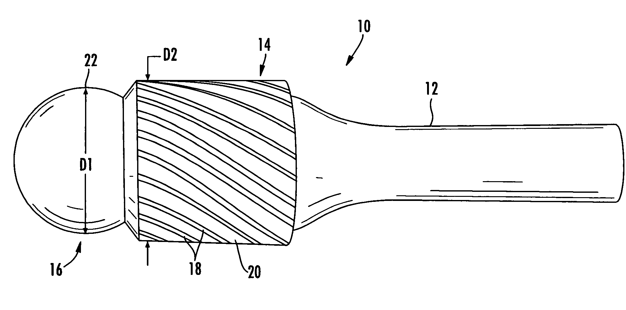
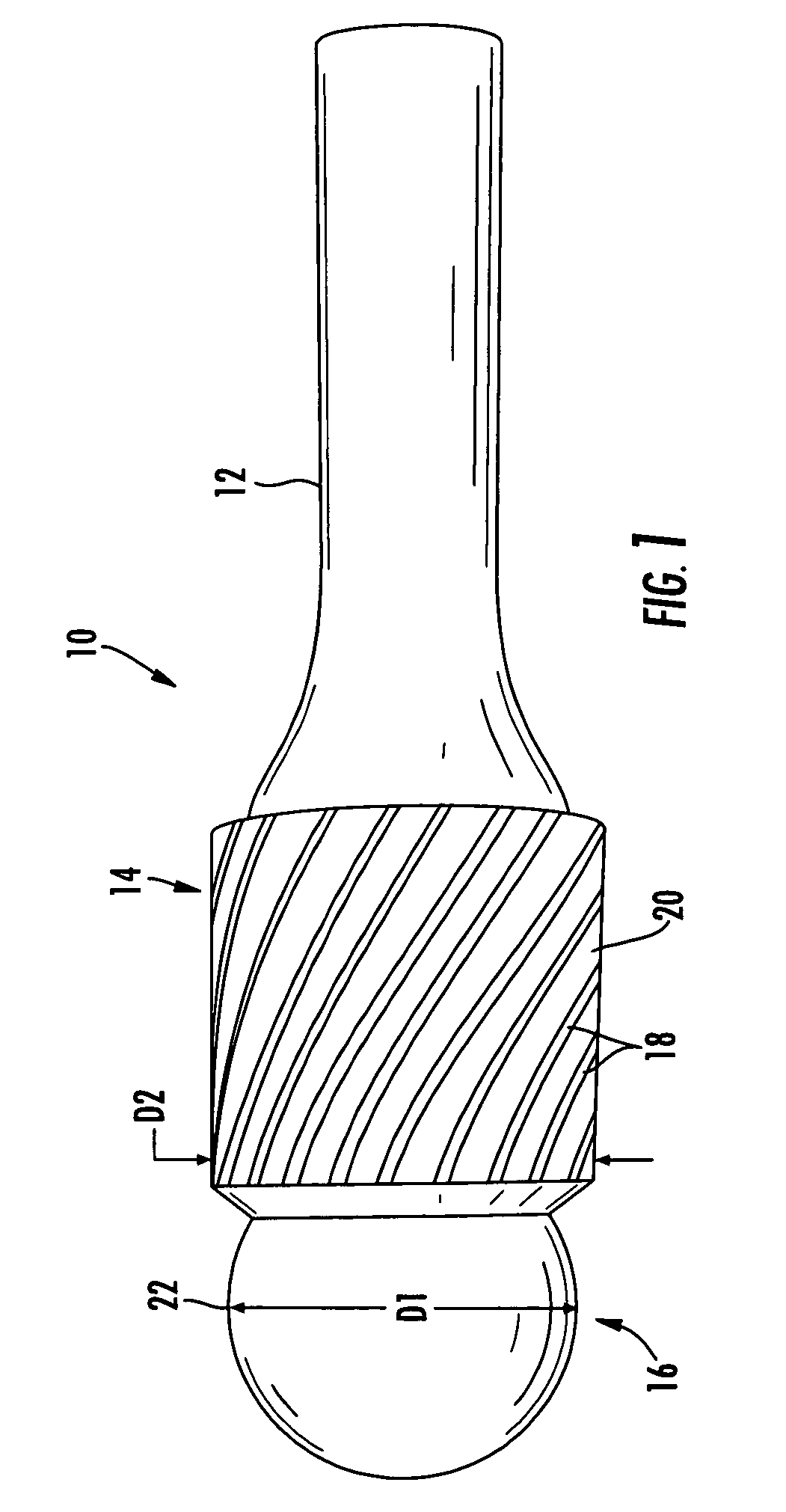
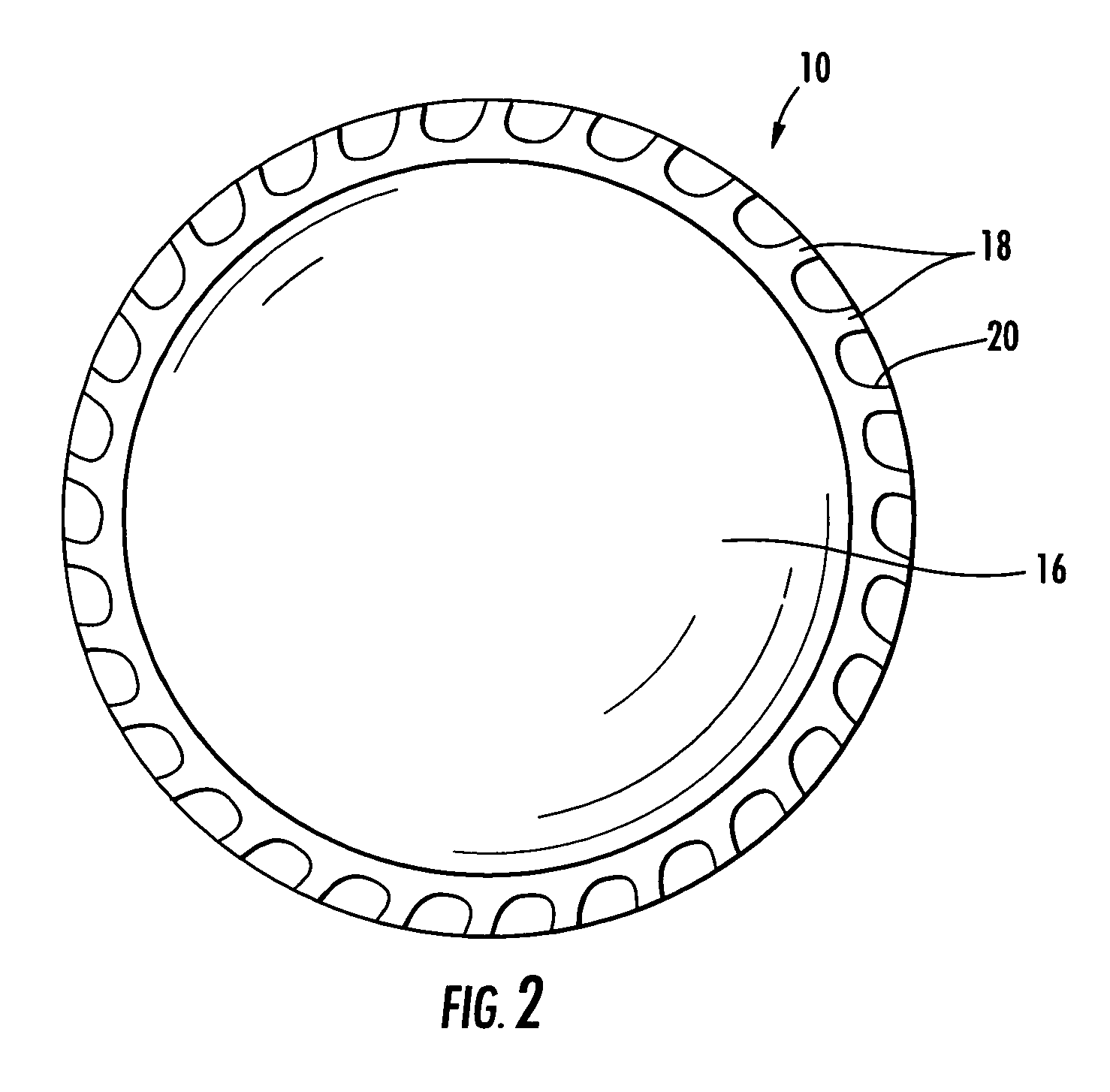
[0021]Referring to the drawings wherein identical reference numerals denote the same elements throughout the various views, FIGS. 1 and 2 depict a rotary file 10 constructed according to an aspect of the present invention. The rotary file 10 comprises a shank 12, a body 14, and a pilot 16. The rotary file 10 may be made from a number of known processes such as casting, forging, machining from billet stock, etc. Typically the rotary file 10 would be a single integral structure, but it could be built up, for example from components brazed or welded together. Nonlimiting examples of suitable materials for the rotary file 10 include tool steels, tungsten carbide, and the like.

[0022]The shank 12 may be cylindrical as shown, or may incorporate retention and / or drive features of a known type, such as a machine taper, threads, or one or more flats, facets, or tabs (not shown).

[0023]The body 14 includes an array of cutting lands 18 separated by flutes 20. In the illustrated example the cutti...


PUM

PropertyMeasurementUnit
restoring forceaaaaaaaaaa
diameteraaaaaaaaaa
of rotationaaaaaaaaaa

Abstract

A rotary file includes: (a) a body having first and second ends, and an outer surface comprising at least one cutting edge; (b) a shank extending from the first end of the body which is adapted to be mounted in a rotary tool; and (c) a pilot extending from the second end of the body, the pilot defining an annular peripheral surface with an arcuate cross-section.

Description

BACKGROUND OF THE INVENTION[0001]This invention relates generally to machine tooling and more particularly to apparatus and methods for deburring operations.[0002]Currently many machined features, such as those found on aircraft engine parts, are deburred manually. This leads to inconsistencies in the finished feature size and shape. With the introduction of requirements for stricter process control, highly stressed features require automated deburring processes to ensure consistency. Because of the difficulty machining aviation materials, many of these features come out of the primary machining operations with large burrs that must be removed with carbide cutters (e.g. rotary files). The difficulty with automating these processes is removing the burr without removing parent material. The burr size varies from part to part and the location of the feature can also vary making it impossible to program a specific toolpath to remove only the burr.[0003]The state of the art for this appl...

Claims


Application Information

Patent Timeline
Patent Type & Authority Patents(United States)
IPC IPC(8): B27C5/00B23C3/12
CPCB23C3/12B23C5/10B23D71/005B23D79/04B25J11/006B23C2210/326B23C2210/70Y10T82/10Y10T409/304256B23C2220/40B27C9/00
Inventor DUBELL, RICHARD E.MANNING, TIMOTHY L.
Owner GENERAL ELECTRIC CO
Why Eureka
Try Eureka