Connector

a technology of connecting parts and connectors, applied in the direction of fixed connections, coupling device connections, engagement/disengagement of coupling parts, etc., can solve problems such as housing damag

Inactive Publication Date: 2010-06-15
JAPAN AVIATION ELECTRONICS IND LTD
View PDF4 Cites 0 Cited by
  • Summary
  • Abstract
  • Description
  • Claims
  • Application Information

AI Technical Summary

Benefits of technology

[0015]The present invention has been made in view of these circumstances, and an object thereof is to provide a connector which is capable of ensuring reliability of contact even when a mating object to be connected, which is fitted to a receiving portion of a housing, is tilted.
[0016]To attain the above object, the present invention provides a connector comprising a housing including a receiving portion for receiving a mating object to be connected, a plurality of first contacts each of which includes a first contact portion protruding into the receiving portion such that the first contact portion is capable of being brought into contact with a first mating contact portion of the mating object to be connected, and a first spring portion that is elastically deformable and supports the first contact portion, the plurality of first contacts being arranged and held in the housing in a direction of length of the housing, a plurality of second contacts each of which includes a second contact portion protruding into the receiving portion such that the second contact portion is capable of being brought into contact with a second mating contact portion of the mating object to be connected, and a second spring portion that is elastically deformable and supports the second contact portion, the plurality of second contacts being arranged and held in the housing in the direction of the length of the housing, and displacement-suppressing means for suppressing displacement of the mating object to be connected, in a contact direction, when the receiving portion has received the mating object to be connected.
[0017]With the arrangement of the connector according to the first aspect of the present invention, the displacement-suppressing means is provided for suppressing displacement of the mating object to be connected in the contact direction when the receiving portion has received the mating object to be connected. Therefore, even if the mating object to be connected is tilted within the receiving portion, the position of the mating object in the contact direction is hardly displaced. Therefore, according to the present invention, it is possible to ensure reliability of contact even when a mating object to be connected, which is fitted to a receiving portion of a housing, is tilted.

Problems solved by technology

A gap between the receptacle-side housing and the plug-side housing formed when the receptacle connector and the plug connector are fitted to each other is small, and therefore when one of the housings is tilted with respect to the fitting direction after the receptacle connector and the plug connector are fitted, there is a fear that the housing is damaged.
However, if the gap is simply increased, when the connectors are fitted, the position of the plug-side housing within the receiving portion of the receptacle connector is displaced in a contact direction.

Method used


Image

  • Connector
  • Connector
  • Connector

Examples


first embodiment

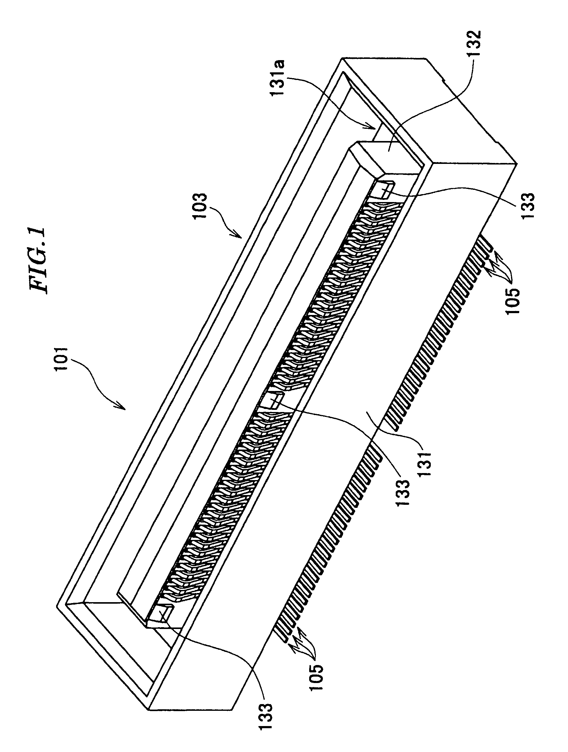
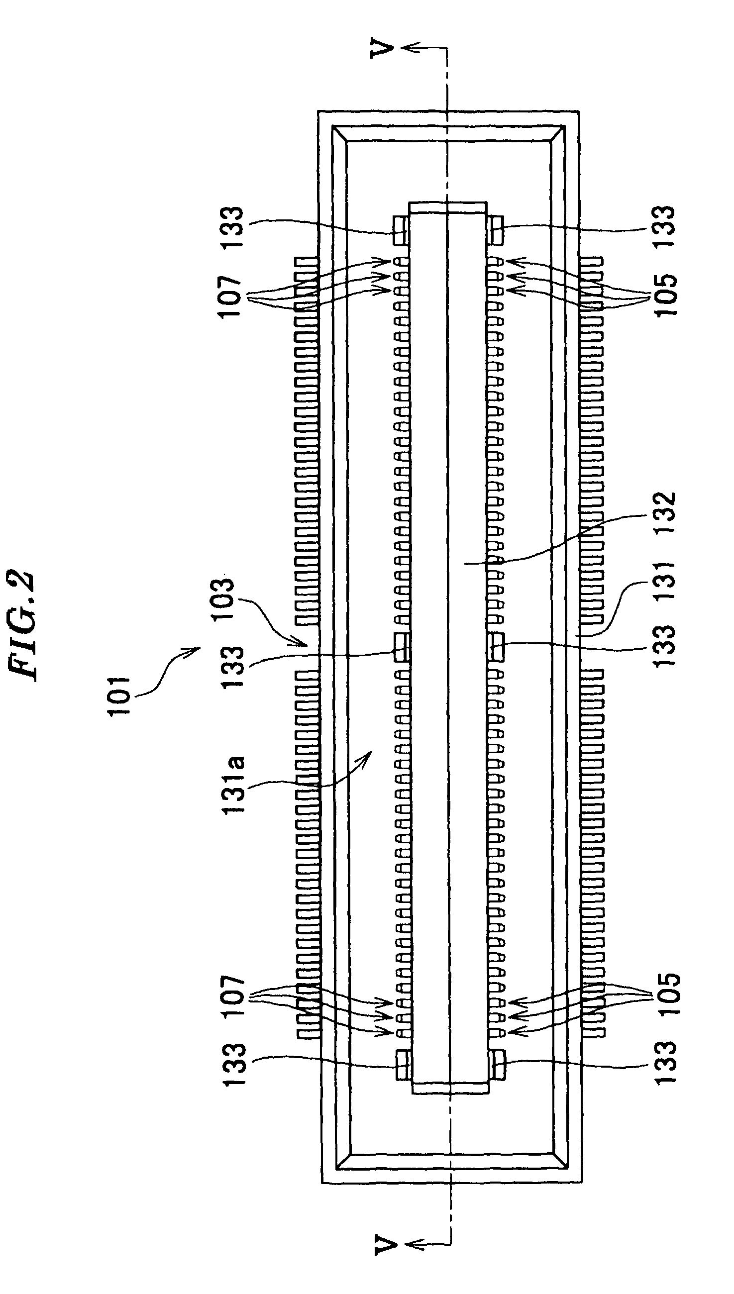
[0056]Referring to FIGS. 1 and 2, a socket-side connector 101 according to the present invention (connector, receptacle-side connector) is comprised of a housing 103, a plurality of first socket-side contacts (first contacts) 105, and a plurality of second socket-side contacts (second contacts) 107.

[0057]The housing 103 includes a casing portion 131 and a protrusion 132.

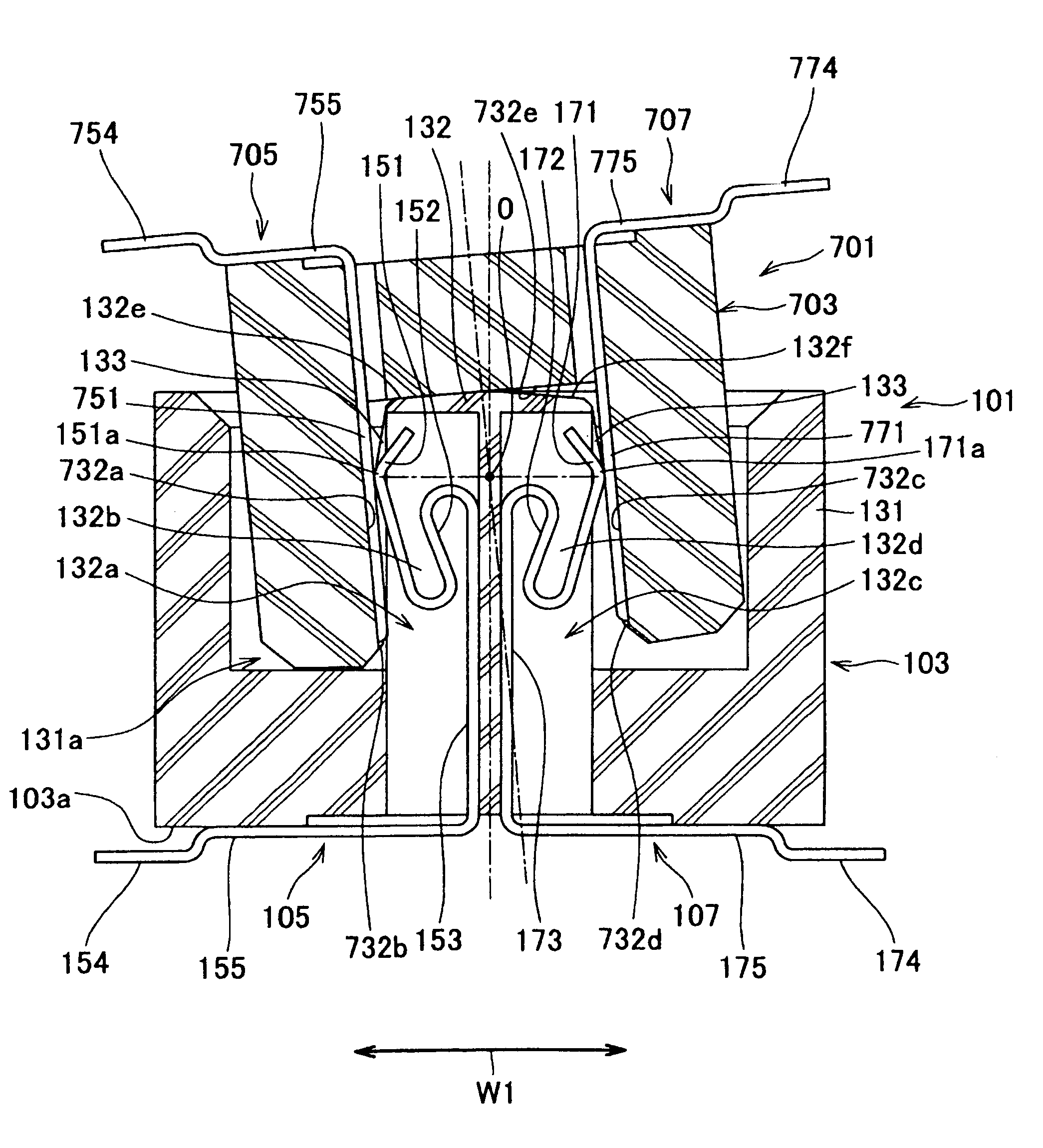
[0058]The casing portion 131 is in the form of a box with an upper surface thereof open, and has a receiving portion 131a. The receiving portion 131a is a space for receiving part of a plug-side connector 701, described hereinafter (see FIG. 8). Gaps G1 and G1 are each formed between an inner surface of the casing portion 131 and an opposed one of outer surfaces of a housing 703 of the plug-side connector 701 such that the plug-side connector 701 received in the receiving portion 131a can move by a predetermined distance in the direction (contact direction) of contact with contact portions 151 and 171, referred to he...

third embodiment

[0107]Next, a card edge connector according to the present invention will be described with reference to FIGS. 20 to 27.

[0108]Referring to FIGS. 20 to 23, the card edge connector (connector) 301 is comprised of a housing 303, a plurality of first contacts 305, and a plurality of second contacts 307.

[0109]The housing 303 includes a receiving portion 331. The receiving portion 331 is a space for receiving one end of the circuit board 901 (see FIGS. 25 and 26). Gaps G7 and G7 are formed between two opposed inner surfaces of the receiving portion 331 and opposite surfaces of the circuit board (mating object to be connected) 901, respectively, such that the circuit board 901 received in the receiving portion 331 can move by a predetermined distance in the direction (contact direction) of contact with contact portions 351 and 371, referred to hereinafter, of the first and second contacts 305 and 307 (see FIGS. 25 and 26). Also in the third embodiment, the contact direction is approximatel...

fourth embodiment

[0135]Next, a card edge connector according to the present invention will be described with reference to FIG. 29.

[0136]The fourth embodiment has approximately the same construction as that of the third embodiment, so that only main component parts different in construction from those of the first embodiment will be described hereinafter.

[0137]Although in the card edge connector 301 according to the third embodiment, the protruding portions 333, which are the displacement-suppressing means, are formed on the inner surfaces of the housing 303, in the card edge connector 401 according to the fourth embodiment, the displacement-suppressing member 409, which is the displacement-suppressing means, is provided as a separate member from a housing 403.

[0138]Displacement-suppressing member accommodating portions 434 are formed at respective opposite ends of the housing 403 in the direction of the length thereof (see FIG. 28). Part of each displacement-suppressing member accommodating portion ...


PUM


Abstract

A connector capable of ensuring reliability of contact even when a mating object to be connected, which is fitted to a receiving portion of a housing, is tilted. The receiving portion for receiving a plug-side connector is formed in the housing. A plurality of first socket-side contacts including contact portions are arranged in the housing. Each contact portion protruding into the receiving portion can be brought into contact with a first plug-side contact of the plug-side connector. A plurality of second socket-side contacts including contact portions are arranged in the housing. Each contact portion protruding into the receiving portion can be brought into contact with a second plug-side contact of the plug-side connector. Protruding portions are formed in the housing, for suppressing displacement of the plug-side connector in the receiving portion.

Description

BACKGROUND OF THE INVENTION[0001]1. Field of the Invention[0002]This invention relates to a connector.[0003]2. Description of the Related Art[0004]Conventionally, there has been proposed a connector comprised of a receptacle connector and a plug connector (see Japanese Laid-Open Patent Publication (Kokai) No. 2005-71769).[0005]The receptacle connector is comprised of a receptacle-side housing including a receiving portion for receiving the plug connector, and a plurality of receptacle-side contacts each held by a corresponding one of two side walls of the receptacle-side housing, opposed to each other via the receiving portion.[0006]Each receptacle-side contact includes a receptacle-side contact portion that is capable of being brought into contact with a plug-side contact portion of the plug connector. The receptacle-side contact portion faces the receiving portion.[0007]The plug connector is comprised of a plug-side housing including a protrusion that is capable of being fitted in...

Claims


Application Information

Patent Timeline
Patent Type & Authority Patents(United States)
IPC IPC(8): H01R12/00
CPCH01R12/716H01R12/51H01R12/71H01R13/62
Inventor KIMURA, MASAKI
Owner JAPAN AVIATION ELECTRONICS IND LTD
Why Eureka
Try Eureka