Expandable power and data center adapted for use with multiple mounts

a data center and expansion port technology, applied in the direction of flexible/turnable line connectors, coupling device connections, instruments, etc., can solve the problems of entanglement of electrical cords and communications wires connected to the devices, the positioning of electrical power outlets and communication ports, and the cost of electrical materials rapidly increasing

Active Publication Date: 2010-06-15
BYRNE NORMAN R
View PDF7 Cites 76 Cited by
  • Summary
  • Abstract
  • Description
  • Claims
  • Application Information

AI Technical Summary

Problems solved by technology

Historically, one problem common to the use of electrical power and communications equipment is the positioning of electrical power outlets and communication ports, such as conventional RS-232 voice / data interface connectors.
However, the cost of electrical materials rapidly increases as the number of power source receptacles and associated equipment is increased.
In addition, and perhaps more importantly, the conventional design of single- or double-unit receptacles (for both electrical power and communications) within walls or floor surfaces, which are often a substantial distance from the devices to be powered or with which to communicate, cause unsightly and sometimes dangerous arrays, and may result in entanglements of the electrical cords and communications wires connected to the devices.
Again, however, the raceways can result in unsightly and entangled arrays of electrical cords and communication lines.
In addition, such raceways are often located on floor surfaces and are not particularly convenient.
Accordingly, these receptacles and communication ports are typically in a fairly open location, and the device cords again may prove to be unsightly and space consuming.
If, alternatively, the receptacles and communication ports are somewhat hidden from view, they can be difficult to access.
That is, the use of springs or similar arrangements can sometimes result in additional repair and maintenance costs.
Further, the use of a relatively long extrusion and spring assemblies can also result in higher initial costs.

Method used


Image

  • Expandable power and data center adapted for use with multiple mounts
  • Expandable power and data center adapted for use with multiple mounts
  • Expandable power and data center adapted for use with multiple mounts

Examples


Embodiment Construction

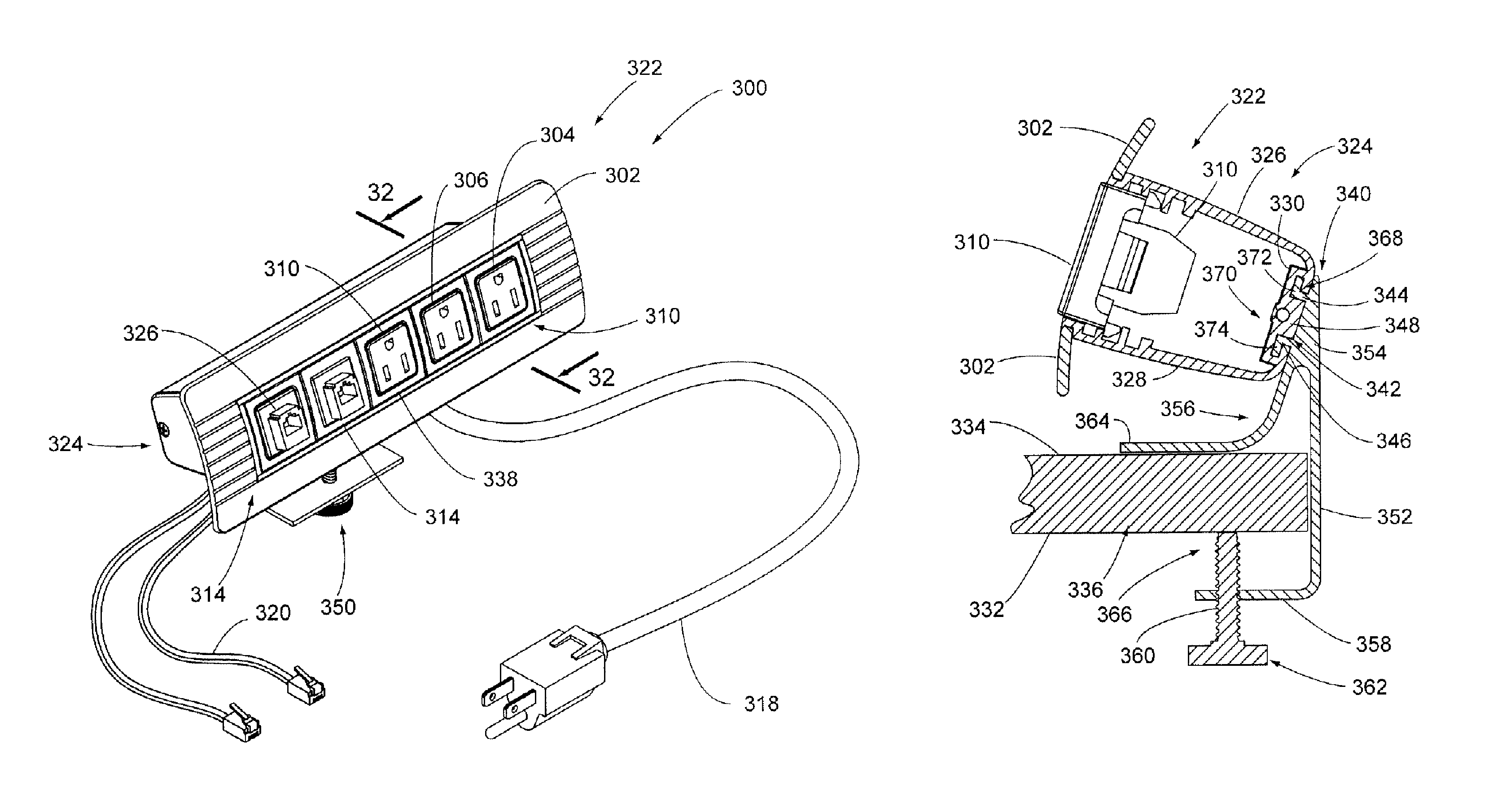
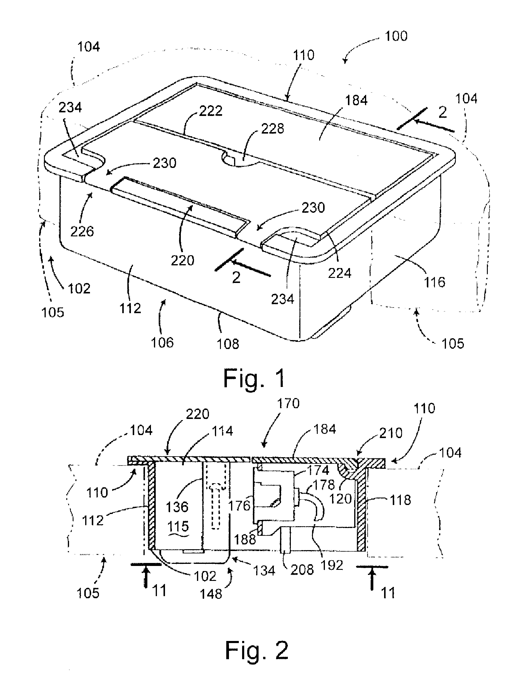
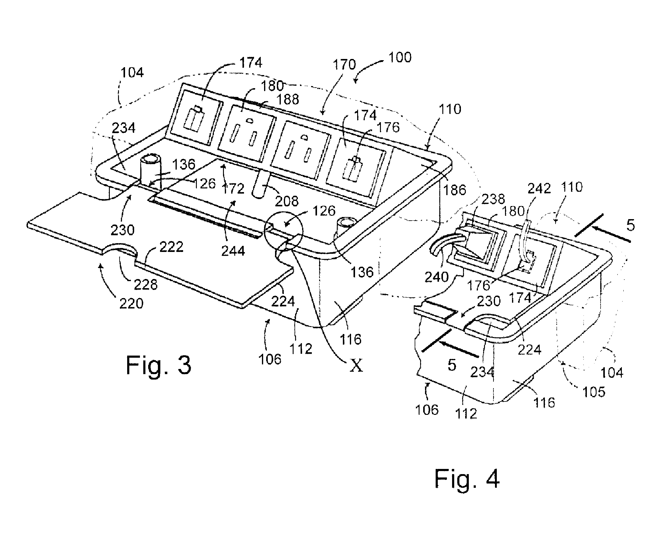
[0074]The principles of the invention are disclosed, by way of example, in an expandable power and data center shown in two embodiments of expandable power and data centers as illustrated in FIGS. 18-38. More specifically, certain of FIGS. 18-38 illustrate an embodiment referred to herein as an expandable power and data center 300. Others of the drawings of FIGS. 18-38 illustrate a second embodiment of a power data center in accordance with the invention, referred to as an expandable power and data center 500. The expandable power and data centers 300, 500 in accordance with the invention provide several advantages over known assemblies. Expandable power and data centers in accordance with the invention comprise means for mounting to elements such as planer work surfaces, vertical side surfaces, movable walls, or other types of comparable elements. In this regard, the expandable power and data centers in accordance with the invention are adapted for use with multiple types of mounts...


PUM


Abstract

An expandable power and data center (300) is mounted to a work surface (332), and includes a front face surface (302). Extending outwardly from an aperture (338) within the face (302) are power receptacles (310) and data ports (312). A housing (322) extends rearwardly of the front face (302) and includes a bracket mount (340). The bracket mount (340) is formed by the rear portion (330) of the housing (322) having a central portion (348) intermediate a set of L-slots (342). The L-slots (342) releasably engage various configurations of mounting brackets (350, 390) for use in mounting the power and data center (300) to various types of surfaces.

Description

CROSS-REFERENCE TO RELATED APPLICATIONS[0001]This application is based on and claims priority of U.S. Provisional Patent Application Ser. No. 60 / 690,020, filed Jun. 13, 2005, and U.S. Provisional Application Ser. No. 60 / 700,526, filed Jul. 19, 2005.STATEMENT REGARDING FEDERALLY SPONSORED RESEARCH OR DEVELOPMENT[0002]Not applicable.REFERENCE TO A MICROFICHE APPENDIX[0003]Not applicable.FIELD OF THE INVENTION[0004]The invention relates to electrical power, and power and data distribution systems and, more particularly, to power and data center systems having capabilities of expansion and further having capabilities of being mounted to work surfaces and the like.DESCRIPTION OF RELATED ART[0005]The use of computers, sophisticated telecommunications equipment and other electronic devices is continuing to rapidly increase in commercial, industrial and other office environments. As a result, the importance of efficiently supplying power throughout these environments is also increasing. His...

Claims


Application Information

Patent Timeline
Patent Type & Authority Patents(United States)
IPC IPC(8): H01R13/60
CPCG06F1/266G06F2200/261
Inventor BYRNE, NORMAN R.
Owner BYRNE NORMAN R
Why Eureka
Try Eureka