Thermally linked molecular sieve beds for CO2 removal

a molecular sieve bed and molecular sieve technology, applied in the direction of separation process, dispersed particle separation, chemistry apparatus and processes, etc., can solve the problems of carbon dioxide exposure, harmful to the health of humans and other mammals, negative effect of adsorption isotherms,

Active Publication Date: 2010-06-15
HAMILTON SUNDSTRAND CORP
View PDF18 Cites 22 Cited by
  • Summary
  • Abstract
  • Description
  • Claims
  • Application Information

AI Technical Summary

Problems solved by technology

Exposure to carbon dioxide (CO2) for extended periods of time can be harmful to the health of humans and other mammals.
As a result, the sorbent beds operate at elevated temperatures, with a negative effect on adsorption isotherms.
However, this increases the complexity of the carbon dioxide removal system.

Method used


Image

  • Thermally linked molecular sieve beds for CO2 removal
  • Thermally linked molecular sieve beds for CO2 removal

Examples


Embodiment Construction

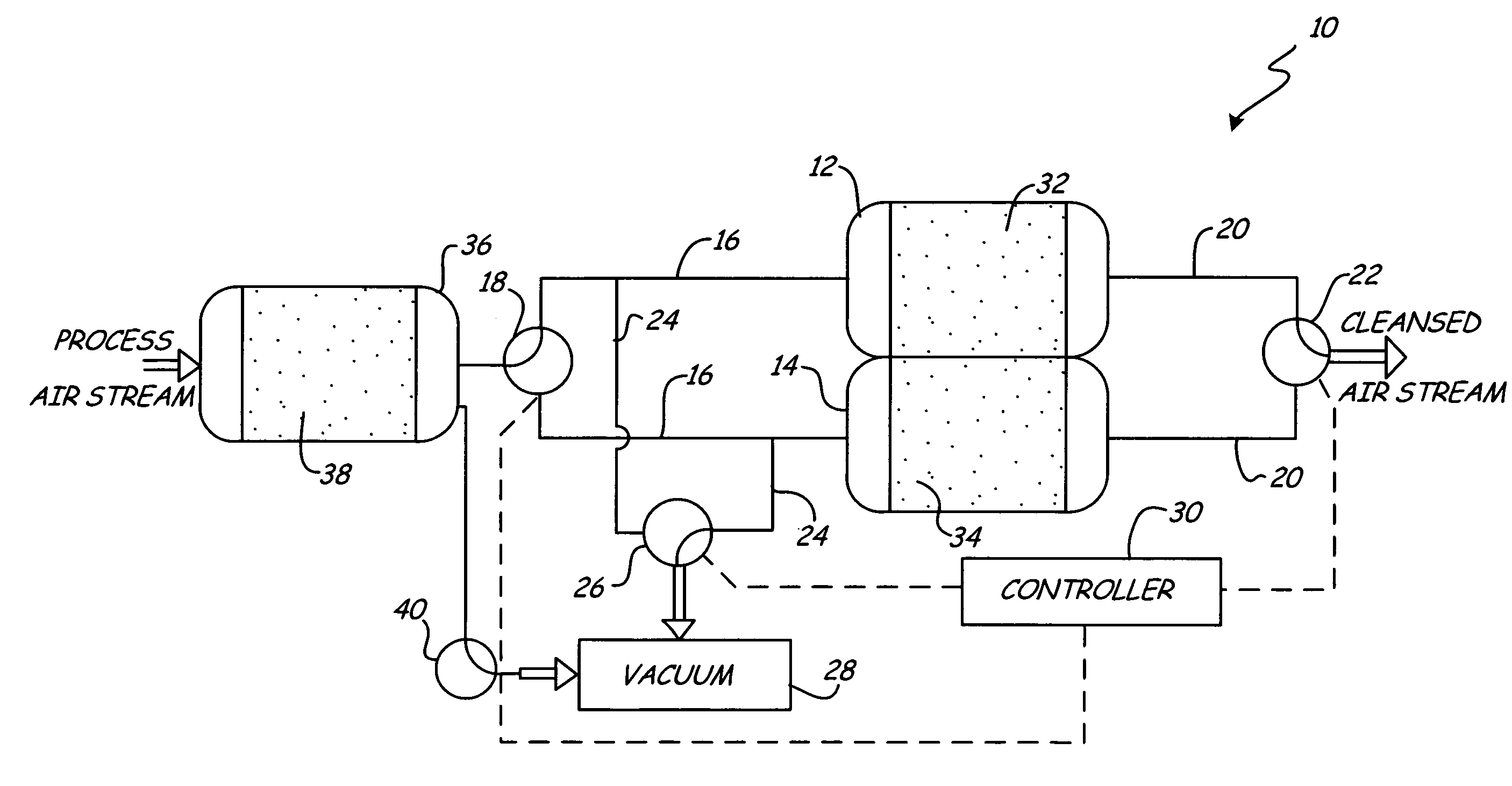
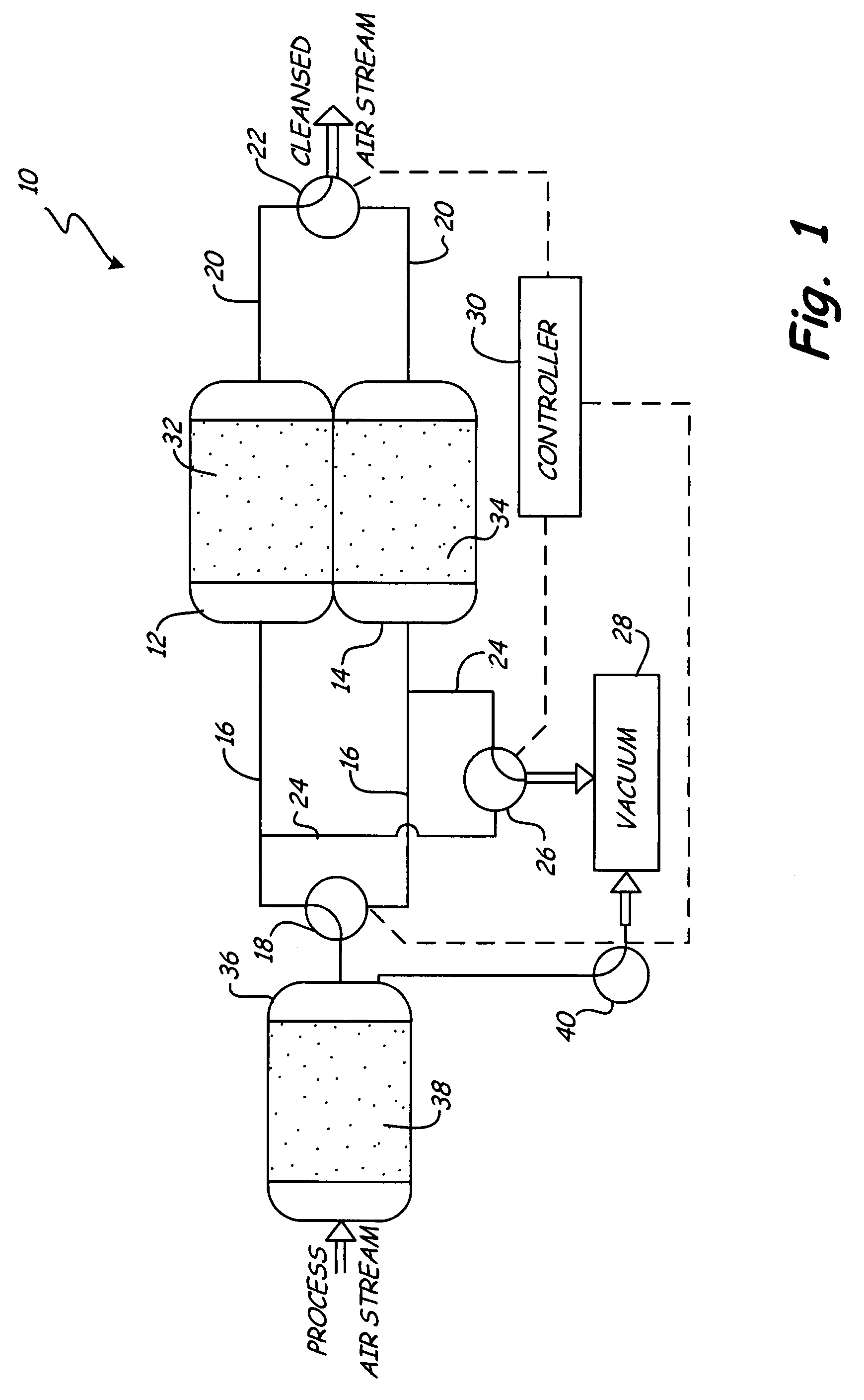
[0007]The sole FIGURE shows a schematic view of carbon dioxide (CO2) removal system 10. CO2 removal system 10 operates substantially isothermally and approximately at ambient temperature and allows an increase in the effective loading of CO2 during the adsorption process. CO2 removal system 10 generally includes a first sorbent bed 12, a second sorbent bed 14, inlet passage 16, inlet valve 18, outlet passage 20, outlet valve 22, carbon dioxide passage 24, carbon dioxide valve 26, vacuum 28, and controller 30. First and second sorbent beds 12 and 14 are thermally linked and heat is transferred between them. The heat extracted from one, adsorbing sorbent bed is used as energy to regenerate the other, desorbing sorbent bed. Because a portion of the energy required for regenerating CO2 removal system 10 is provided by heat transfer between the adsorbing sorbent bed and the desorbing sorbent bed, the overall regeneration power requirement of CO2 removal system 10 is reduced. In an exempl...


PUM

PropertyMeasurementUnit
adsorptionaaaaaaaaaa
temperatureaaaaaaaaaa
pressureaaaaaaaaaa

Abstract

A carbon dioxide (CO2) removal system includes a first sorbent bed and a second sorbent bed. Each of the first and second sorbent beds has a molecular sieve sorbent for adsorbing or desorbing CO2. One of the sorbent beds adsorbs CO2 and the other of the sorbent beds desorbs CO2. The first and second sorbent beds are thermally connected to transfer heat between the sorbent beds.

Description

BACKGROUND OF THE INVENTION[0001]The present invention relates generally to the field of carbon dioxide removal. In particular, the present invention relates to the removal of carbon dioxide using molecular sieves.[0002]Exposure to carbon dioxide (CO2) for extended periods of time can be harmful to the health of humans and other mammals. Thus, a carbon dioxide concentration level of less than approximately 1% is typically maintained in enclosed environments, such as submarines, spacecrafts, or space suits. Current methods of removing carbon dioxide from the air include using solid carbon dioxide sorbents including, but are not limited to: soda lime, zeolites, molecular sieves, solid oxides, alkali metal carbonates, alkali metal hydroxides, amines, and combinations thereof. A specific example of a carbon dioxide removal system using an amine as the sorbent is discussed in U.S. Pat. No. 6,364,938 (assigned to Hamilton Sundstrand Corporation), which is incorporated herein by reference....

Claims


Application Information

Patent Timeline
Patent Type & Authority Patents(United States)
IPC IPC(8): B01D53/02
CPCB01D53/0454B01D53/0476B01D2253/108B01D2257/504B01D2259/65B01D2259/41Y02C10/08B01D2259/4575B01D2259/402Y02C20/40
Inventor NALETTE, TIMOTHY A.RECTOR, TONY
Owner HAMILTON SUNDSTRAND CORP
Why Eureka
Try Eureka