Instrument stand with variable supporting positions

a technology of instrument stands and supporting positions, which is applied in the direction of instruments, stands/trestles, kitchen equipment, etc., can solve the problems of limited space for adjusting positions, difficult to increase the number of pedals between two supporting pods, and the limited space of instrument stands, so as to achieve flexible space usage and simplify installation.

Active Publication Date: 2010-06-15
REMARKABLE
View PDF11 Cites 11 Cited by
  • Summary
  • Abstract
  • Description
  • Claims
  • Application Information

AI Technical Summary

Benefits of technology

[0008]An objective of the invention is to provide an instrument stand with variable ground contact positions of its supporting pods. Using the design of separated combining elements and supporting base, the orientations of the supporting pods can be adjusted before the combining elements are installed on the supporting base. Therefore, the space usage is more flexible. During the assembly, each supporting pod is first fixed on the corresponding combining element. The combining elements are then disposed on the supporting base of the positioning ring. The invention thus has a simpler installation. Moreover, the supporting pods will not be carelessly damaged during assembly.

Problems solved by technology

In addition to suitable disposition space, its space usage is very limited.
For example it is difficult to increase the number of pedals between two supporting pods to two because of the limited space.
Therefore, such an instrument stand has the restriction of limited space to adjust positions for other instruments.
Although more space is allowed for the two pedals, the installation procedure is complicated.
Its stability is worse than the above-mentioned instrument stand with three pods.
It should be mentioned that the above-mentioned two conventional instrument stands have the same problem during their assembly.
When another supporting pod is to be installed on the positioning ring, the installed supporting pod is likely to be damaged.
The fact that these supporting pods cannot be installed independently causes problems for installation.

Method used


Image

  • Instrument stand with variable supporting positions
  • Instrument stand with variable supporting positions
  • Instrument stand with variable supporting positions

Examples


Embodiment Construction

[0019]The present invention will be apparent from the following detailed description, which proceeds with reference to the accompanying drawings, wherein the same references relate to the same elements.

[0020]Please refer to FIGS. 1 to 4 for the structure according to the preferred embodiment of the invention. This example is used to explain the spirit of the invention, but should not be used to restrict the scope thereof.

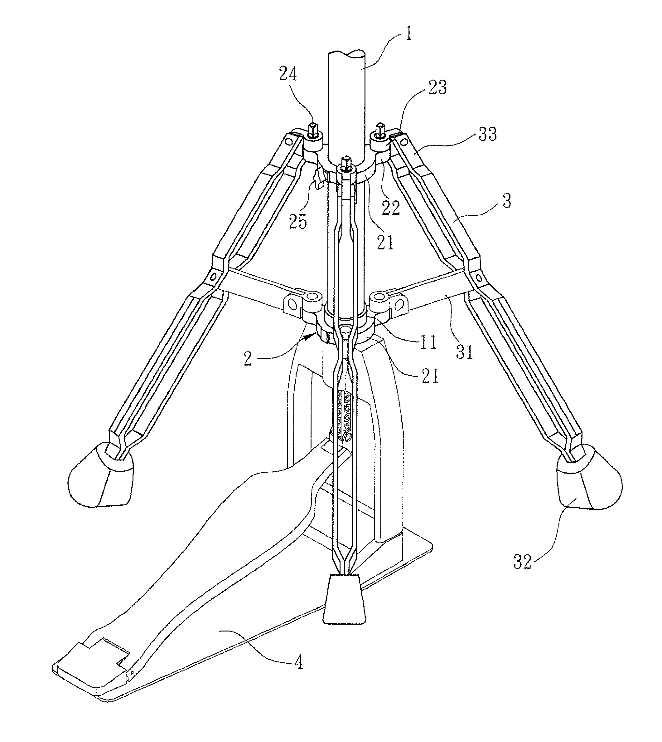
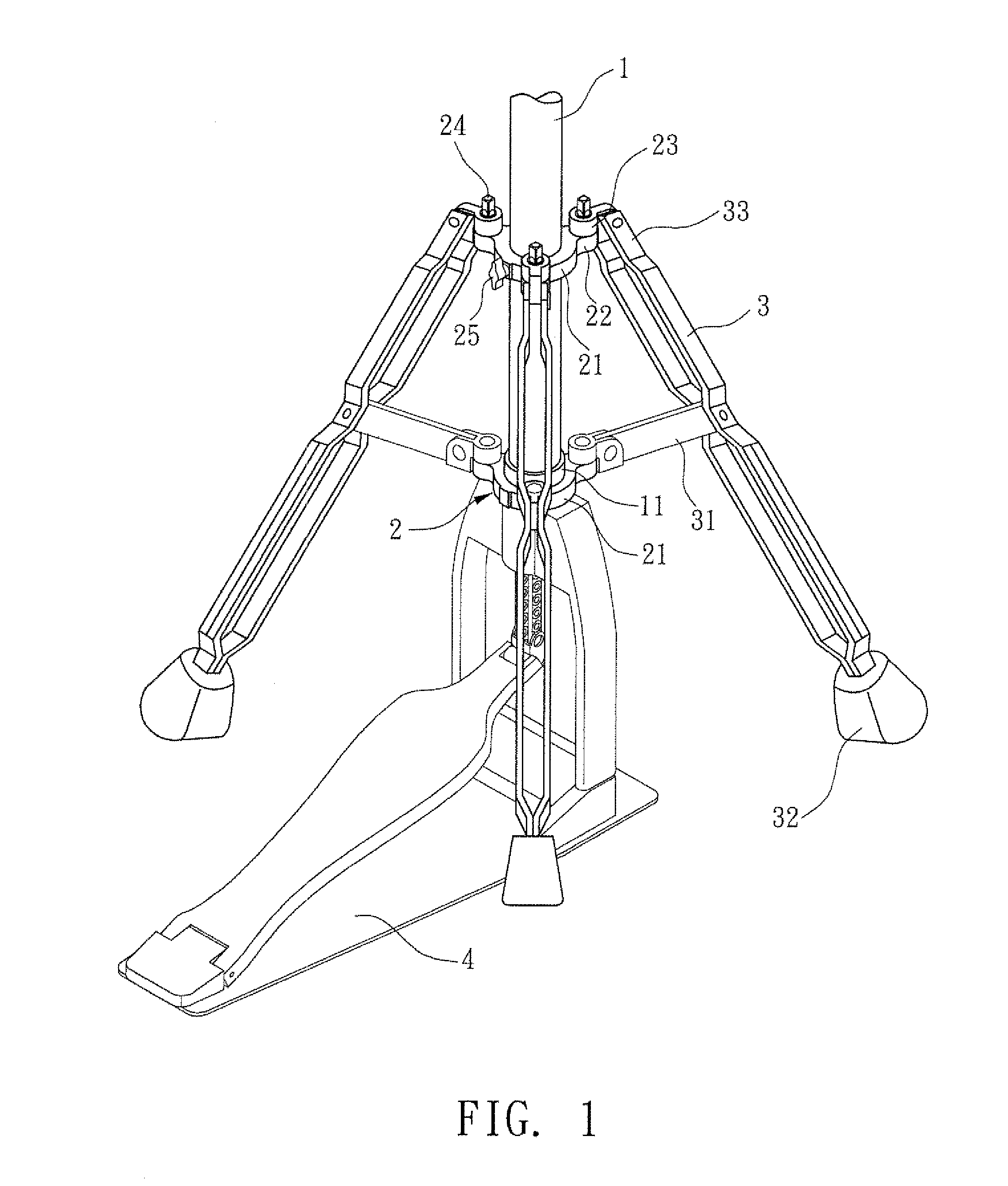
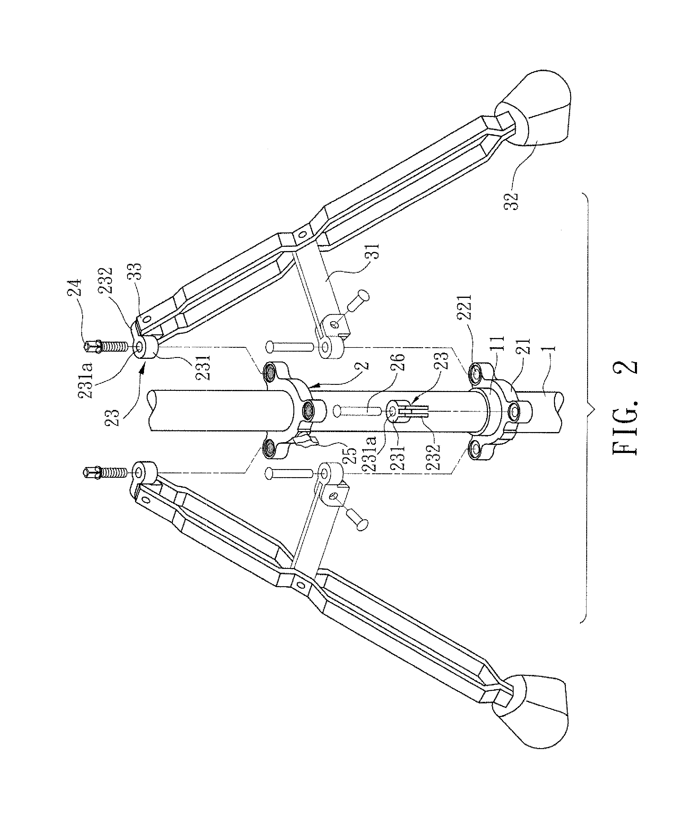
[0021]This embodiment of the invention provides an instrument stand with variable ground contact positions of its supporting pods. It includes a standing post 1, two positioning rings 2, and several supporting pods 3.

[0022]The standing post 1 is mounted with a tool for the music player to use. In this embodiment, the tool is a jazz drum with a cymbal (not shown). The bottom of the instrument stand has a pedal 4 that connects to the hits the cymbal.

[0023]The two positioning rings 2 are mounted around the lower portion of the standing post 1. One of them is fixed, and...


PUM


Abstract

An instrument stand with variable ground contact positions of its supporting pods is disclosed. It has a standing post mounted with two positioning rings. One of them is fixed, and the other can slide relative to the former. The positioning rings have several supporting bases and several connecting elements that fix with the supporting bases after angle adjustment. The supporting pods are locked on the two positioning rings. Each supporting pod is controlled by the relative motion of the two positioning rings to expand and collapse. The ground contact positions of the supporting pods of the invention are thus variable.

Description

BACKGROUND OF THE INVENTION[0001]1. Field of Invention[0002]The invention relates to an instrument stand and, in particular, to an instrument stand with variable ground contact positions of the supporting pods.[0003]2. Related Art[0004]Please refer to U.S. Pat. No. 6,329,584. The three supporting pods of that invention have fixed relative angles. In addition to suitable disposition space, its space usage is very limited. For example it is difficult to increase the number of pedals between two supporting pods to two because of the limited space. Therefore, such an instrument stand has the restriction of limited space to adjust positions for other instruments.[0005]Please refer to U.S. Pat. No. 6,278,046. In order to accommodate the two pedals, the instrument stand in that invention has only two supporting pods. Although more space is allowed for the two pedals, the installation procedure is complicated. Its stability is worse than the above-mentioned instrument stand with three pods....

Claims


Application Information

Patent Timeline
Patent Type & Authority Patents(United States)
IPC IPC(8): G10D13/02
CPCG10D13/065
Inventor CHANG, MING YI
Owner REMARKABLE
Why Eureka
Try Eureka