Systems and methods for estimating time corresponding to peak signal amplitude

a technology of peak signal amplitude and system and method, applied in the field of storage media, can solve the problems of expensive equipment and time for servo writers

Inactive Publication Date: 2010-06-15
BROADCOM INT PTE LTD
View PDF8 Cites 23 Cited by
  • Summary
  • Abstract
  • Description
  • Claims
  • Application Information

AI Technical Summary

Problems solved by technology

Traditionally, the servo data within wedges 160, 165 has been written by an external servo writer which is costly both in terms of equipment and time.

Method used


Image

  • Systems and methods for estimating time corresponding to peak signal amplitude
  • Systems and methods for estimating time corresponding to peak signal amplitude
  • Systems and methods for estimating time corresponding to peak signal amplitude

Examples


Embodiment Construction

[0022]The present invention is related to storage media. More particularly, the present invention is related to systems and methods for preparing servo data on a storage medium.

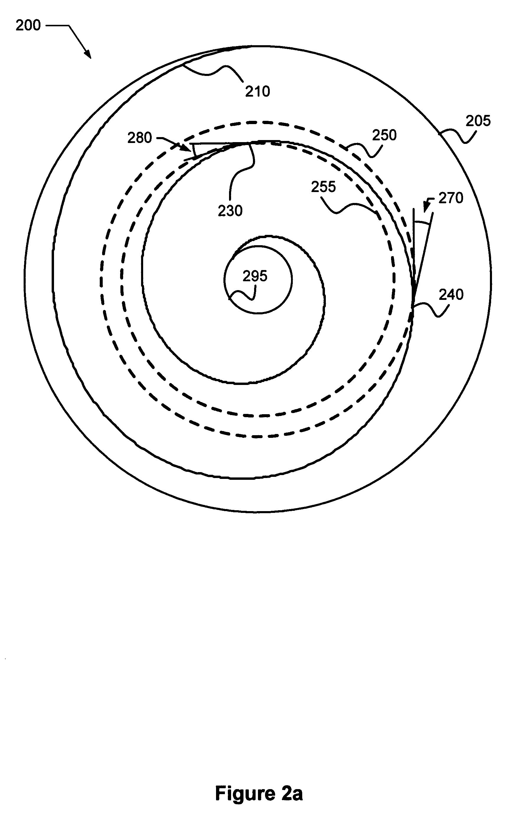
[0023]Turning to FIG. 2a, a storage medium 200 is depicted with a spiral reference pattern 210 formed thereon. In one particular case, the spiral reference pattern includes a repeating pattern of a preamble and servo address mark. In addition, two tracks 250, 255 are also shown on storage medium 200 as dashed lines. Tracks 250, 255 may be formed as concentric circles on storage medium 200 at known distances from an outer edge 205 of storage medium 200. The data stored on storage medium 200 may be serially arranged along tracks 250, 255. It should be noted that a much larger number of tracks may be used in accordance with embodiments of the present invention and that the depiction of only two tracks is intended to simplify the description.

[0024]As shown, spiral reference pattern 210 extends in a smooth spiral ...


PUM

PropertyMeasurementUnit
anglesaaaaaaaaaa
timeaaaaaaaaaa
angleaaaaaaaaaa

Abstract

Various systems and methods for peak signal detection. As one example, a method for peak signal detection that includes receiving a signal is disclosed. The received signal includes a signal region where the signal is increasing in amplitude, another signal region where the signal is decreasing in amplitude, and a transitional signal region coupling the first two signal regions. In some cases, the transitional region is of zero duration and the signal transitions directly from the increasing region to the decreasing region. The method further include calculating a distance between the signal region of increasing amplitude and the signal region of decreasing amplitude, and determining a peak of the received signal that is one half the distance from the signal region of increasing amplitude.

Description

BACKGROUND OF THE INVENTION[0001]The present invention is related to storage media. More particularly, the present invention is related to systems and methods for preparing servo data on a storage medium.[0002]A typical digital magnetic storage medium includes a number of storage locations where digital data may be stored. Data is written to the medium by positioning a read / write head assembly over the medium at a selected location, and subsequently passing a modulated electric current through the head assembly such that a corresponding magnetic flux pattern is induced in the storage medium. To retrieve the stored data, the head assembly is positioned anew over the track. In this position, the previously stored magnetic flux pattern induces a current in the head assembly that can be converted to the previously recorded digital data.[0003]The storage locations on the magnetic storage medium are typically arranged as a serial pattern along concentric circles known as tracks. FIG. 1 sh...

Claims


Application Information

Patent Timeline
Patent Type & Authority Patents(United States)
IPC IPC(8): G11B5/09G11B21/02
CPCG11B5/59661G11B20/10009G11B5/59666G11B2020/1282
Inventor ANNAMPEDU, VISWANATHBLOSS, KEITH R.DING, TIANYANGGRUNDVIG, JEFFREY P.NEVILLE, ROY S.
Owner BROADCOM INT PTE LTD
Why Eureka
Try Eureka