Siding gauge device for staple gun

a gauge device and staple gun technology, applied in the direction of manufacturing tools, paper/cardboard containers, instruments, etc., can solve the problems of user time-consuming and awkward tasks, considerable risk of injury, etc., and achieve the effect of reducing the time for aligning each fastener, improving safety, and improving safety

Active Publication Date: 2010-06-22
GRANT KEVIN ANTHONY
View PDF13 Cites 9 Cited by
  • Summary
  • Abstract
  • Description
  • Claims
  • Application Information

AI Technical Summary

Benefits of technology

[0011]By providing flanges which are able to be slid along the channel of the siding and which are moveable with the safety tip of the staple gun, the present invention both increases safety and decreases the time for aligning each fastener as nothing requires insertion within the apertures in the nailing flange. Furthermore by providing suitably spaced depending flanges which permit engagement along the bottom edge of the channel rather than the top edge for aligning each staple to be dispensed within a respective fastener aperture, the force applied to the staple gun to simply maintain contact of the depending flange with the bottom edge of the channel on the siding thus acts to encourage an upward force on the siding to maintain the siding under tension and further encourage better securement between adjacent rows of siding panels.

Problems solved by technology

In order to properly align the tool however one of the projections must be aligned with and received within one of the apertures in the nailing flange, representing a time consuming and awkward task for a user to do repetitively when installing vinyl siding.
Accordingly there is a considerable risk of injury when using the staple gun by the teachings of Krowl.

Method used


Image

  • Siding gauge device for staple gun
  • Siding gauge device for staple gun
  • Siding gauge device for staple gun

Examples


Embodiment Construction

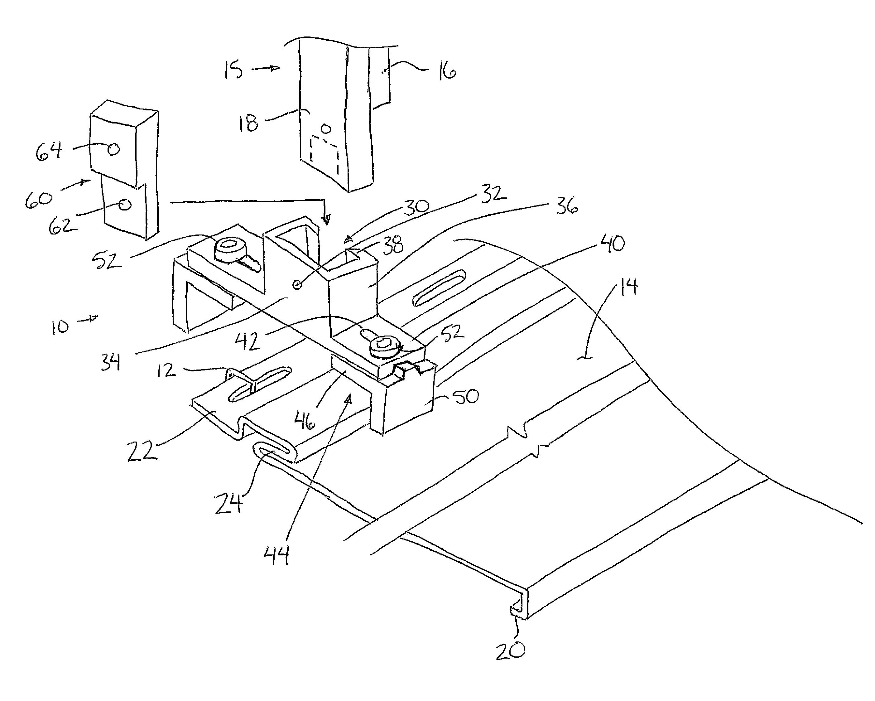
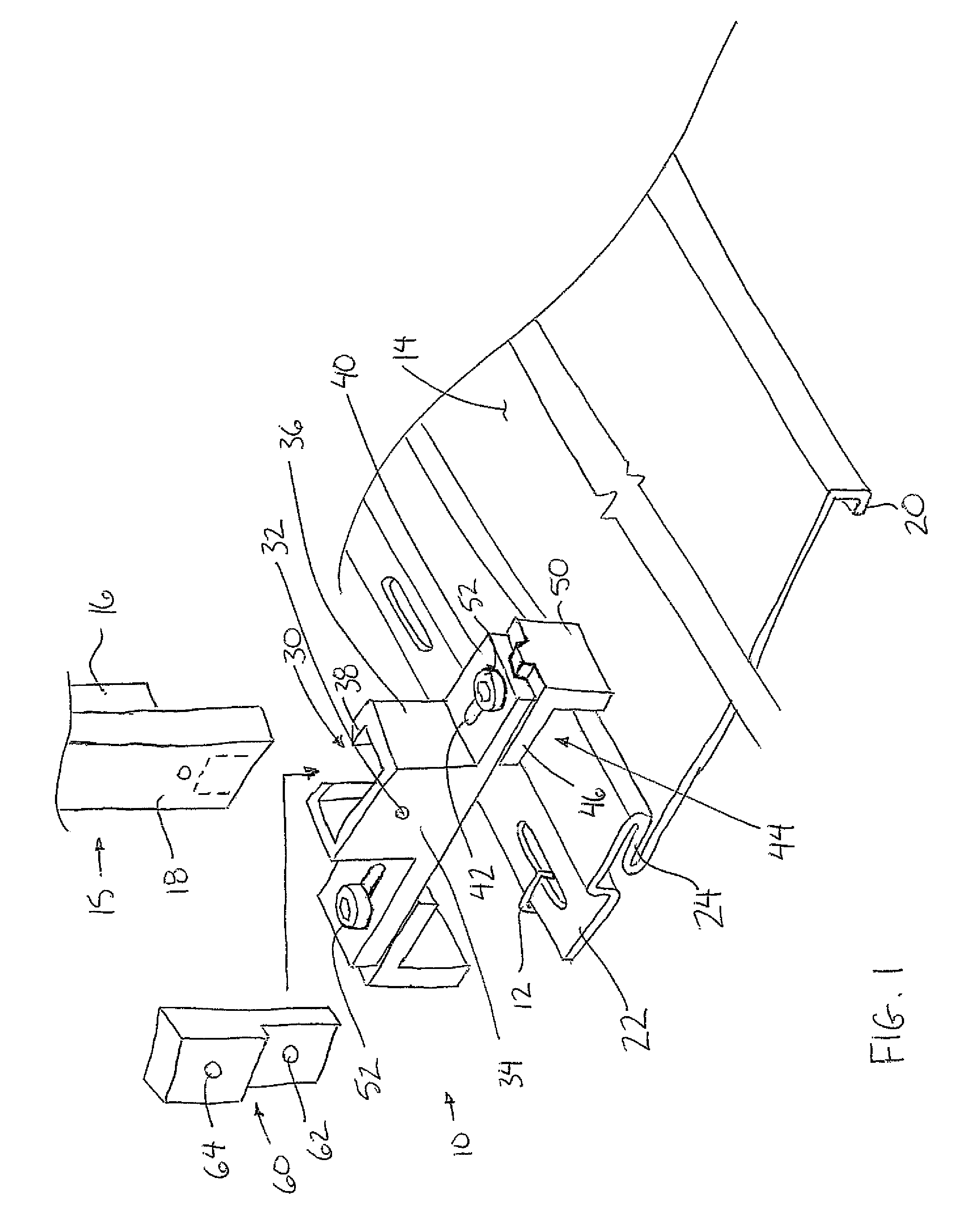
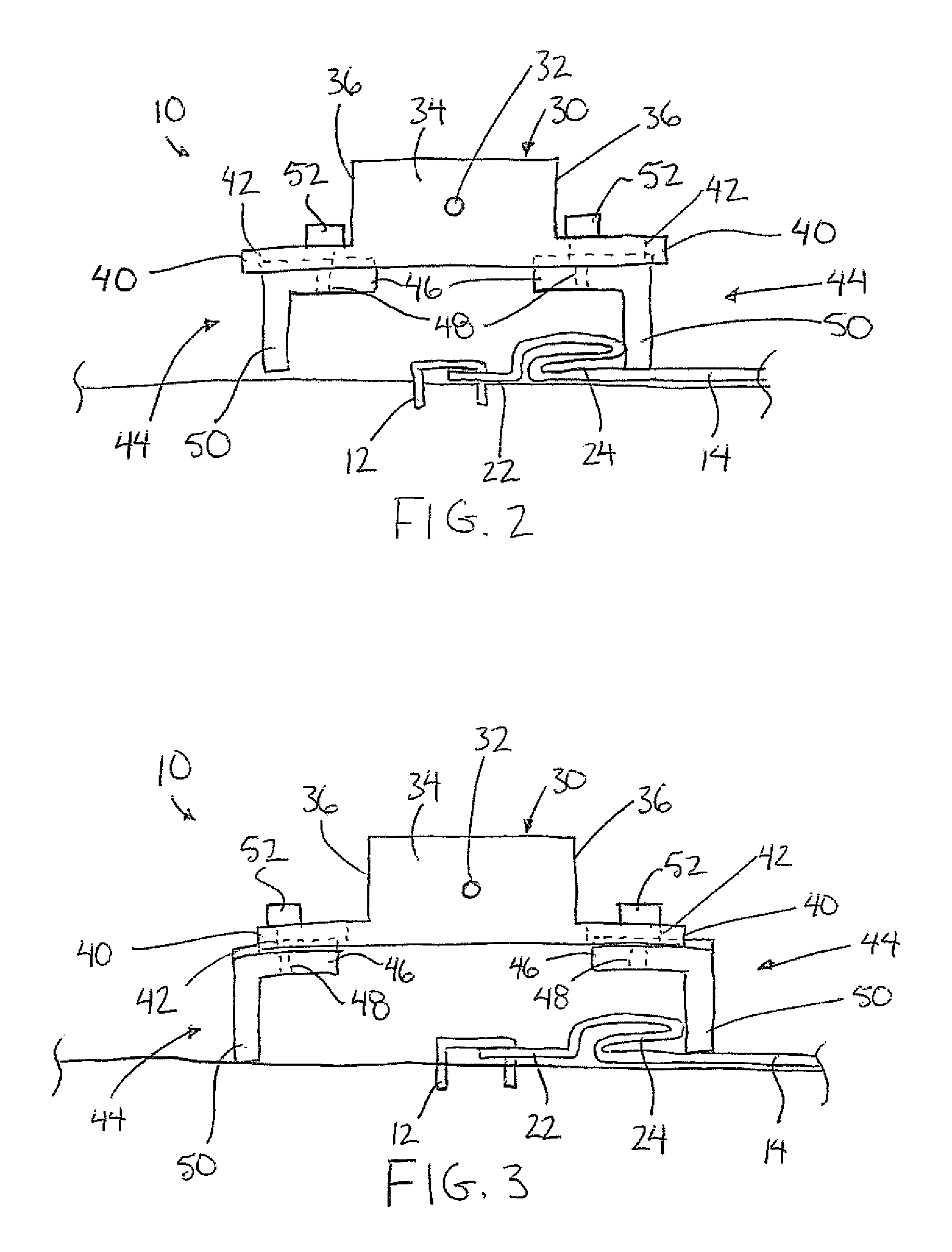
[0032]Referring to the accompanying figures there is illustrated a siding gauge device generally indicated by reference numeral 10. The device 10 is particularly suited for aligning staples 12 with interlocking siding panels 14, for example vinyl siding panels and the like.

[0033]The staples 12 are typically dispensed from a powered staple gun 15 including a dispensing head 16 for dispensing the staples therefrom upon actuation. The dispensing head 16 includes a safety tip 18 which is moveable in relation to the body of the staple gun. The safety tip 18 comprises a switch which is actuated only when the safety tip is contacted against a surface to receive a staple therein as the gun body is advanced towards the surface so that the safety tip is retracted towards the gun body. Once the safety tip is actuated, the trigger of the staple gun becomes activated and permits a staple to be dispensed. The device 10 is suitably arranged for attachment to the safety tip 18 of the dispensing hea...


PUM


Abstract

A gauge device for use with a staple gun serves to align the staple gun relative to building siding to dispense a two prong staple from a head of the staple gun into one of a plurality of fastener apertures in siding members of the building siding. The gauge device comprises a pair of flanges arranged to depend from laterally opposed sides of the head of the staple gun at a location such that abutment of one of the flanges below a lock edge channel of a siding member locates one prong of the two prong staple to be in alignment with one of the fastener apertures and locates the other prong of the two prong staple above the top free edge of a nailing flange of the siding member.

Description

[0001]This application claims foreign priority benefits from Canadian Patent Application 2,588,719, filed May 10, 2007.FIELD OF THE INVENTION[0002]The present invention relates to a gauge for aligning a staple gun with siding, and more particularly relates to a gauge which is suited for use with interlocking siding, for example vinyl siding and the like.BACKGROUND[0003]Interlocking siding, for example vinyl siding and the like, is a common exterior finish for various buildings. Vinyl siding typically comprises a profile representing two or three overlapping siding boards in appearance as a single integral panel. A hook is formed along a bottom edge of the panel opposite a nailing flange extending along the top edge of the panel. A plurality of apertures are provided in the nailing flange at spaced positions along the top edge. A channel or lock edge is formed along the top edge of the panel also, just below the nailing flange. The channel is arranged to matingly receive the hook at ...

Claims


Application Information

Patent Timeline
Patent Type & Authority Patents(United States)
IPC IPC(8): B25C7/00B23Q17/22G01B21/00
CPCB25C7/00
Inventor GRANT, KEVIN ANTHONY
Owner GRANT KEVIN ANTHONY
Why Eureka
Try Eureka