Ultrasonic fingerprint scanning utilizing a plane wave

a plane wave and ultrasonic technology, applied in the field of ultrasonic biometric readers, can solve problems such as deficiencies in ultrasonic systems, and achieve the effect of facilitating image collection and obtaining images faster

Active Publication Date: 2010-06-22
QUALCOMM INC
View PDF33 Cites 100 Cited by
  • Summary
  • Abstract
  • Description
  • Claims
  • Application Information

AI Technical Summary

Benefits of technology

[0010]A phased array of piezoelectric transducer elements can be used to both steer and focus an ultrasound pulse to a target area pixel in a raster scanning process. This may be attractive from a manufacturing perspective in that it may allow the electronic focusing and steering of an ultrasound pulse and avoid the mechanical positioning and alignment required in present ultrasound scanning systems.
[0011]In an embodiment of the invention, a platen and a finger may receive ultrasonic wave energy and the reflected energy may be detected and converted to an image of the finger by means of an array of detecting elements. In a line array configuration, information about the fingerprint may be acquired by moving the line array detector and collecting image information one line at a time. A line area detector may be used with a line array generator or an area array generator. A system without moving components may be constructed and the finger may be dragged across the platen to allow the image to be collected. Alternatively, by providing an area array detector and an area array generator, an image may be obtained faster, and the user need not be required to move his finger in order to facilitate image collection.

Problems solved by technology

Although using ultrasound to produce an image of a fingerprint may be superior in detail to a similar image collected by an optical system or other means, existing ultrasound systems have deficiencies.

Method used


Image

  • Ultrasonic fingerprint scanning utilizing a plane wave
  • Ultrasonic fingerprint scanning utilizing a plane wave
  • Ultrasonic fingerprint scanning utilizing a plane wave

Examples


Embodiment Construction

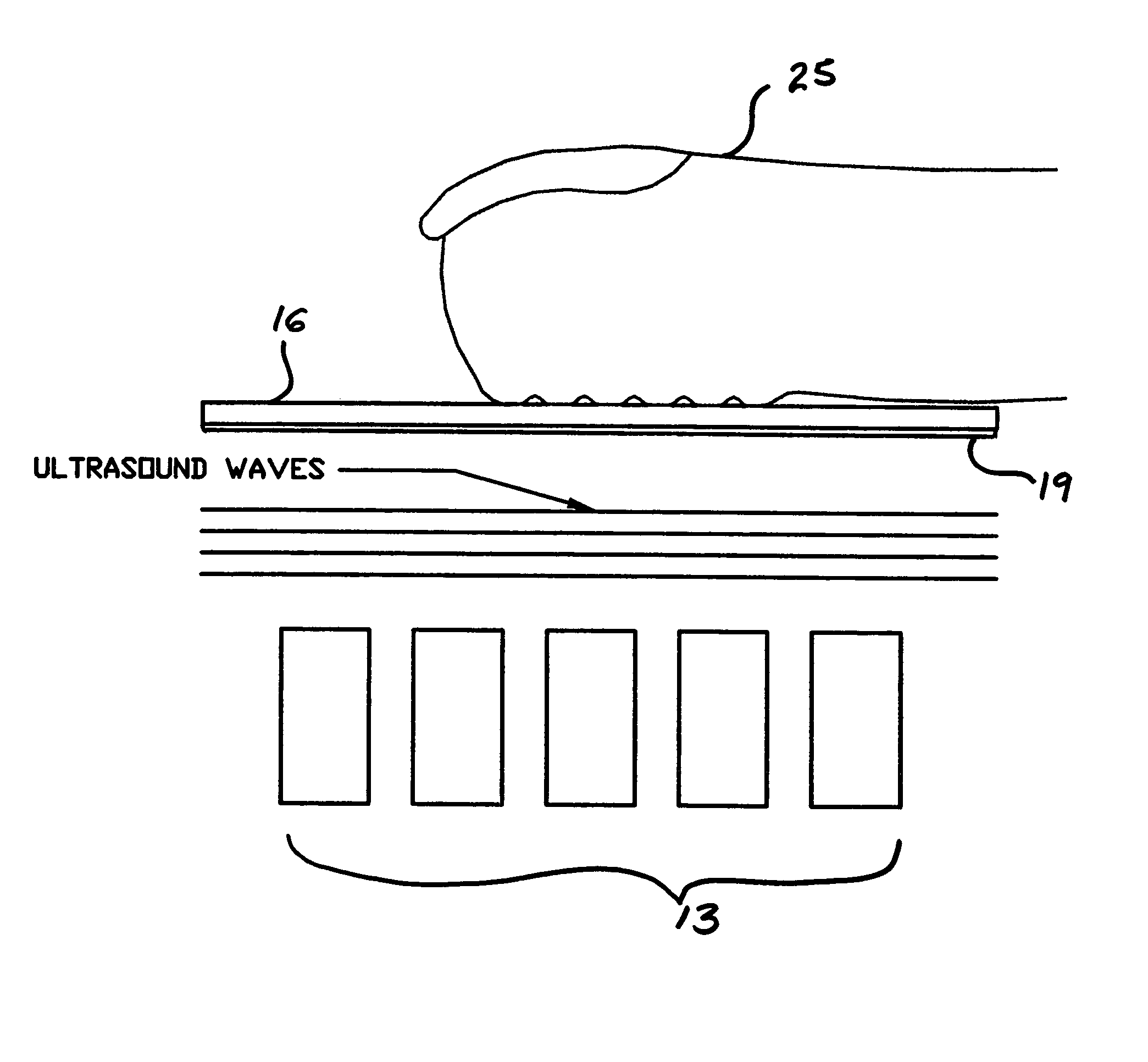
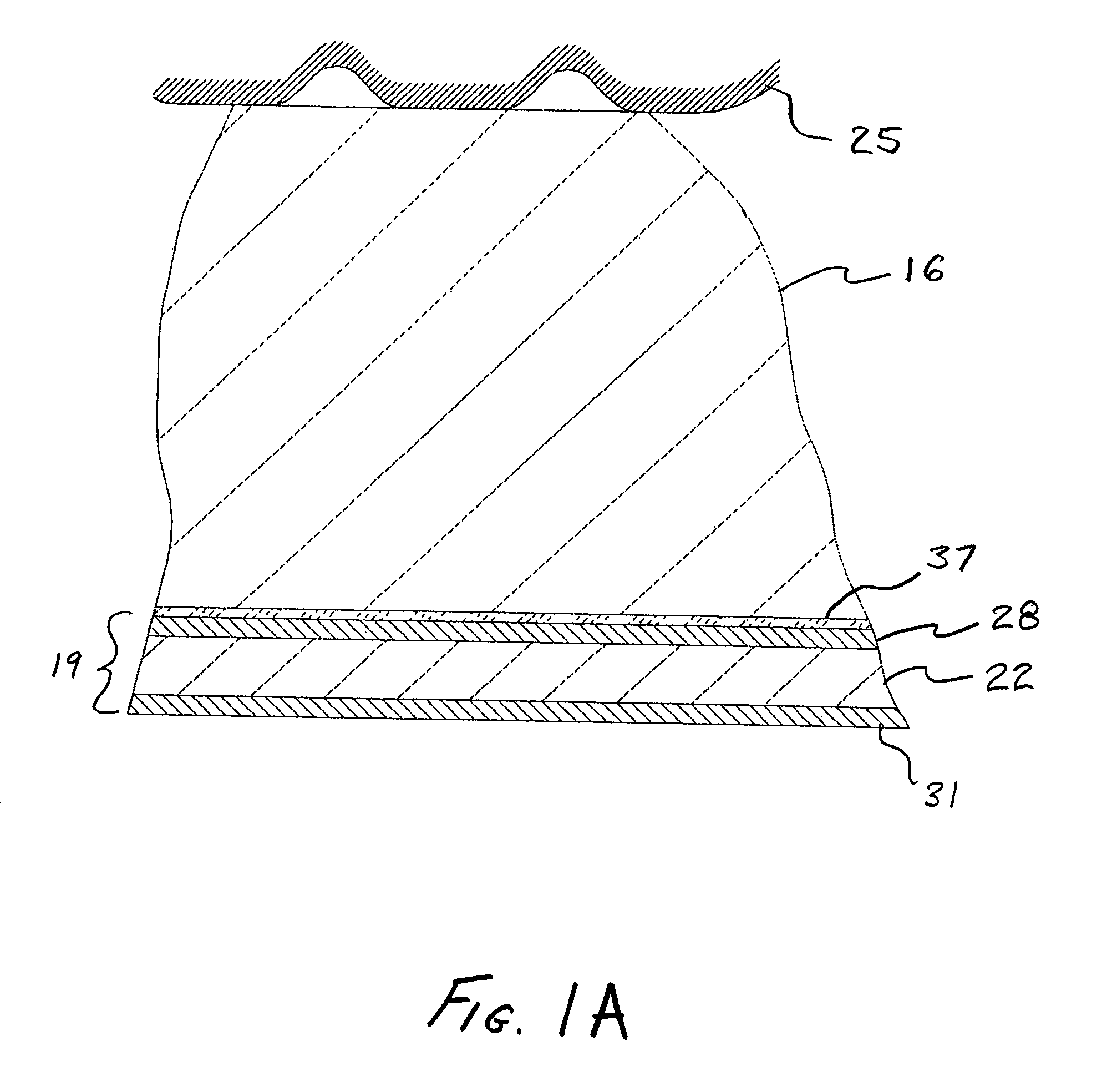
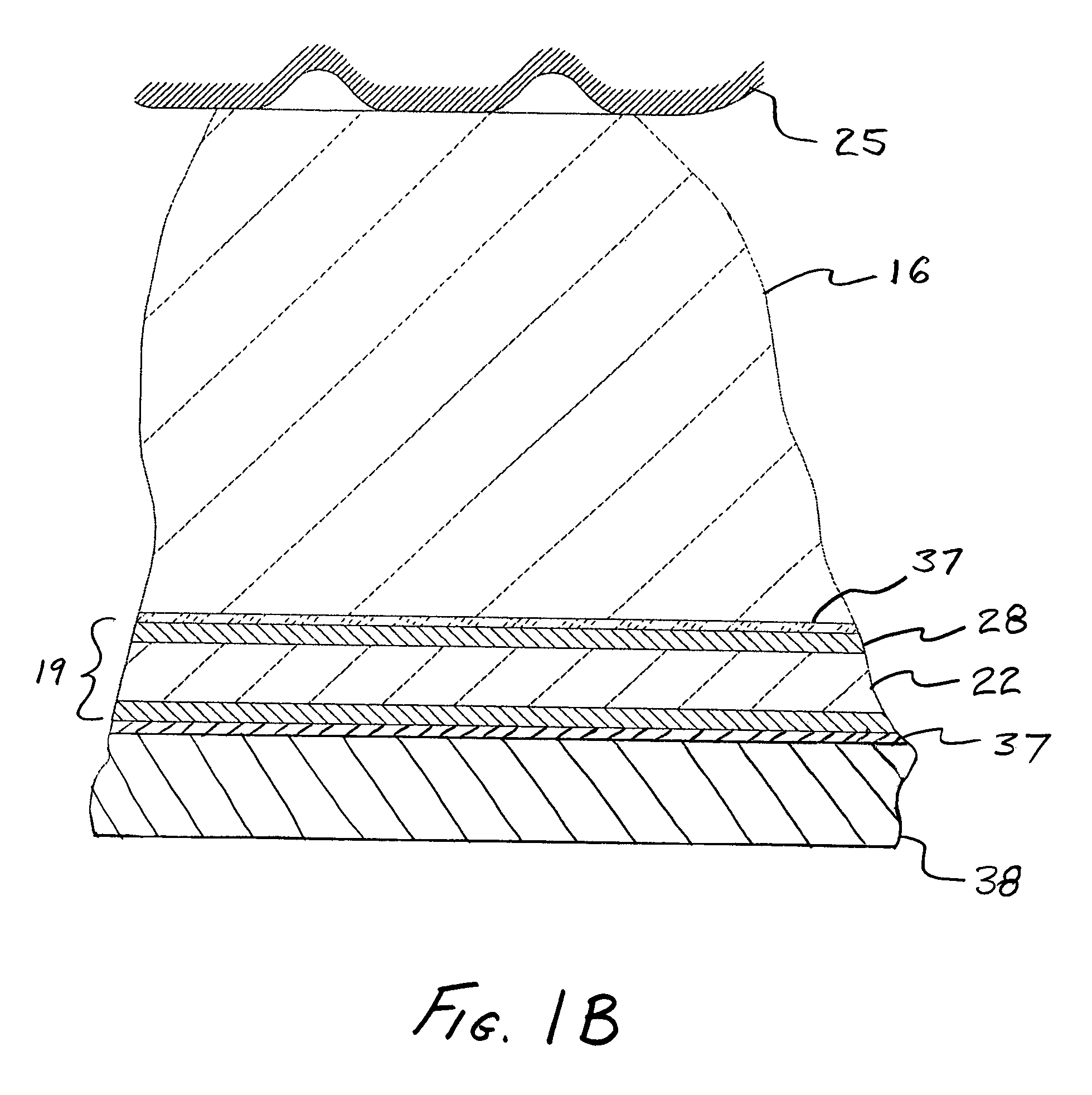
[0032]The invention may be embodied as a fingerprint scanner 10. Such a scanner 10 may have an ultrasonic wave detector 13, a platen 16 and an ultrasonic wave generator 19 located between the detector 13 and the platen 16. The generator 19 may include a piezoelectric film 22. Pulse waves may be generated by applying a voltage to the piezoelectric film 22 to expand or contract the film 22, depending upon the charge applied, to generate a plane pulse-wave. The voltage may be applied to the film 22 via a first electrode 28 and a second electrode 31. In this fashion, an ultrasound wave pulse may be made by changing the volume occupied by the film. This pulse-wave travels toward the finger, passes through the platen 16, and is reflected from the finger 25, passes back through the platen 16, through the first electrode 28, film 22, and second electrode 31 until it strikes the detector 13.

[0033]The detector 13 and the generator 19 may be separated. A fluidic transmission medium 33 may be l...


PUM

PropertyMeasurementUnit
length-aaaaaaaaaa
to-width aaaaaaaaaa
piezoelectricaaaaaaaaaa

Abstract

The invention may be embodied as a fingerprint scanner having an ultrasonic wave detector, a platen, an ultrasonic wave generator located between the detector and the platen. The invention may be embodied as a method of scanning a finger. One such method includes providing a platen, a detector and a generator, the generator being placed between the platen and the detector. A finger may be provided on the platen, and an ultrasound wave pulse may be sent from the generator toward the finger. The wave pulse may be reflected from the finger, and received at the detector. The received wave pulse may be used to produce an image of the finger.

Description

CROSS-REFERENCE TO RELATED APPLICATION[0001]This application claims the benefit of priority to U.S. provisional patent application Ser. No. 60 / 616,953, filed on Oct. 7, 2004.FIELD OF THE INVENTION[0002]The present invention relates to ultrasonic biometric readers, such as fingerprint scanners.BACKGROUND OF THE INVENTION[0003]Since the 1800's fingerprint information has been collected from human fingers and hands by means of ink and paper. For the purposes of this document, the term “fingerprint” is used to mean the skin surface friction ridge detail of a portion of a hand, such as a single fingerprint, or the entire hand. In recent years various electronic fingerprint scanning systems have been developed utilizing optical, capacitance, direct pressure, thermal and ultrasonic methods. Methods based on ultrasound have proven to be highly accurate, since they are insulated from the effects of grease, dirt, paint, ink and other image contaminants.[0004]In an ultrasonic system, a piezoel...

Claims


Application Information

Patent Timeline
Patent Type & Authority Patents(United States)
IPC IPC(8): G01N29/00G06K9/00
CPCA61B5/1172A61B8/0858G01N29/2437G06K9/0002G06K9/00026A61B8/4483G06V40/1335G06V40/1306
Inventor SCHNEIDER, JOHN K.KITCHENS, JACK C.BAKER, JAMES T.
Owner QUALCOMM INC
Why Eureka
Try Eureka