System, method, and apparatus for downhole submersible pump having fiber optic communications

a technology of fiber optic communication and submersible pumps, which is applied in the field of system, method and apparatus of electrical submersible pumps equipped with fiber optic communication, can solve the problems of large space, large amount of data acquisition equipment, and high cost of each method

Active Publication Date: 2010-06-22
BAKER HUGHES INC
View PDF13 Cites 40 Cited by
  • Summary
  • Abstract
  • Description
  • Claims
  • Application Information

AI Technical Summary

Benefits of technology

[0013]One embodiment of a fiber optic system, method, and apparatus for downhole submersible pumps includes a surface panel near the well head that provides a laser light source. The invention includes means for examining a well cavity from each of the discrete sensors (e.g., Fabry-Perot, Bragg-Grating, etc.) on a fiber optic cable, and / or another system capable of measuring distributed temperature sensors (DTS). In one embodiment, the fiber optic cable comprises a multi-mode fiber and / or one or more single-mode fibers. The multi-mode fiber allows for light transmission to the DTS sensor system that is generally located below the pump and motor within the well bore. This design permits the DTS to form a profile of the temperature gradients from the pump / motor down through the perforations of the well.
[0014]In one embodiment, the single-mode fiber allows light communications to sensors (e.g., Fabry-Perot) that are located, for example, above and below the pump and motor. The upper sensor monitors pressure and temperature from the tubing and / or casing transmitting the fluid to the surface. The lower sensor is fabricated into a component that is integral with the motor assembly. It monitors motor temperature, which is critical for proper electrical submersible pump (ESP) operation. The sensor's configuration allows the sensor to be placed as close as possible to the motor end turns within the motor oil. Also, as ESPs require seal sections that equalize the pressure inside and outside the motor, the pressure measured is the pressure of the well (e.g., at the seal at the motor oil depth). The sensor section that is integral with the motor supports the weight of the tubing or other supporting rods for the DTS sensor array.

Problems solved by technology

Each of these methods is expensive.
Moreover, the wire line methods occur at large time intervals and cannot provide continuous information about the well bore condition or that of the surrounding formations.
In turn, this requires a large amount of power, data acquisition equipment and relatively large space in the well bore, all of which may be impractical or prohibitively expensive.
Because of the harsh operating conditions downhole, it is difficult for the electronics used in conventional downhole sensors to survive for any extended period of time.
In addition, electrical cables are subject to degradation under these conditions.
In addition, due to long electrical path lengths for downhole devices, cable reactance / resistance becomes significant unless large cables are used.
This is difficult to do within the limited space available in production strings.
In addition, due to the high reactance / resistance, power requirements also become large.
One of the most common drawbacks of employing the method above noted with respect to injection wells is commonly identified as “breakthrough”.
Moreover, other geologic conditions such as faults and unconformities also affect the in-situ sweep efficiency.
While careful examination of the formation by skilled geologists can yield a reasonable understanding of the characteristics thereof and therefore deduce a plausible scenario of the way the flood front will move, it has not heretofore been known to monitor precisely the location of the flood front as a whole or as individual sections thereof.
However, it can be difficult to monitor and control such chemical injection in real time.
Likewise, it can be difficult to monitor and control such treatment in real time.

Method used


Image

  • System, method, and apparatus for downhole submersible pump having fiber optic communications
  • System, method, and apparatus for downhole submersible pump having fiber optic communications
  • System, method, and apparatus for downhole submersible pump having fiber optic communications

Examples


Embodiment Construction

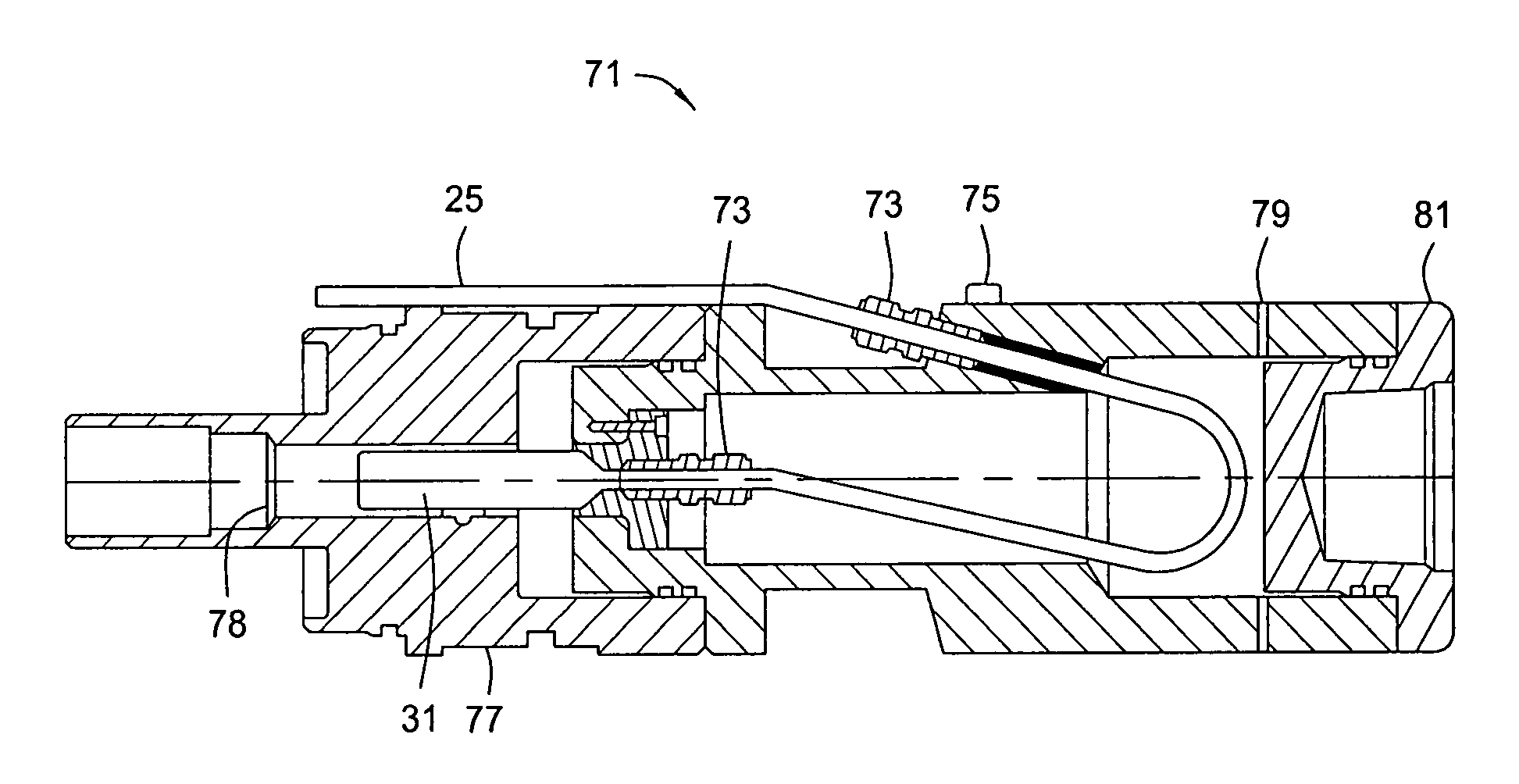
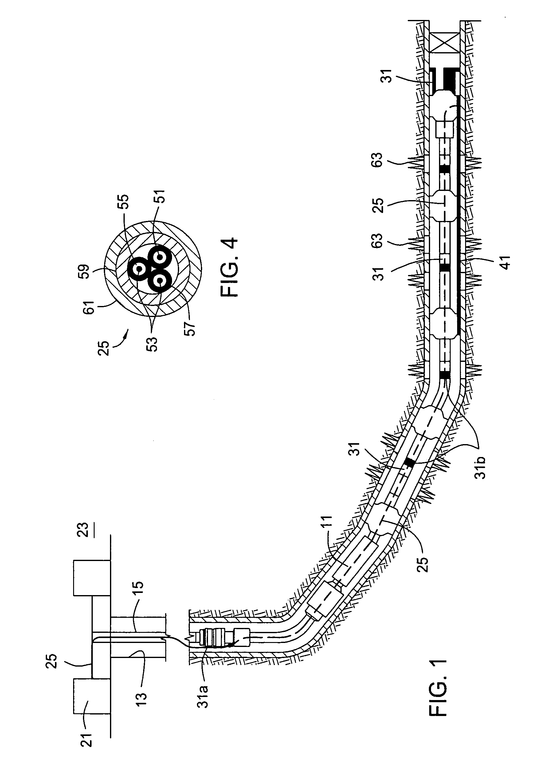
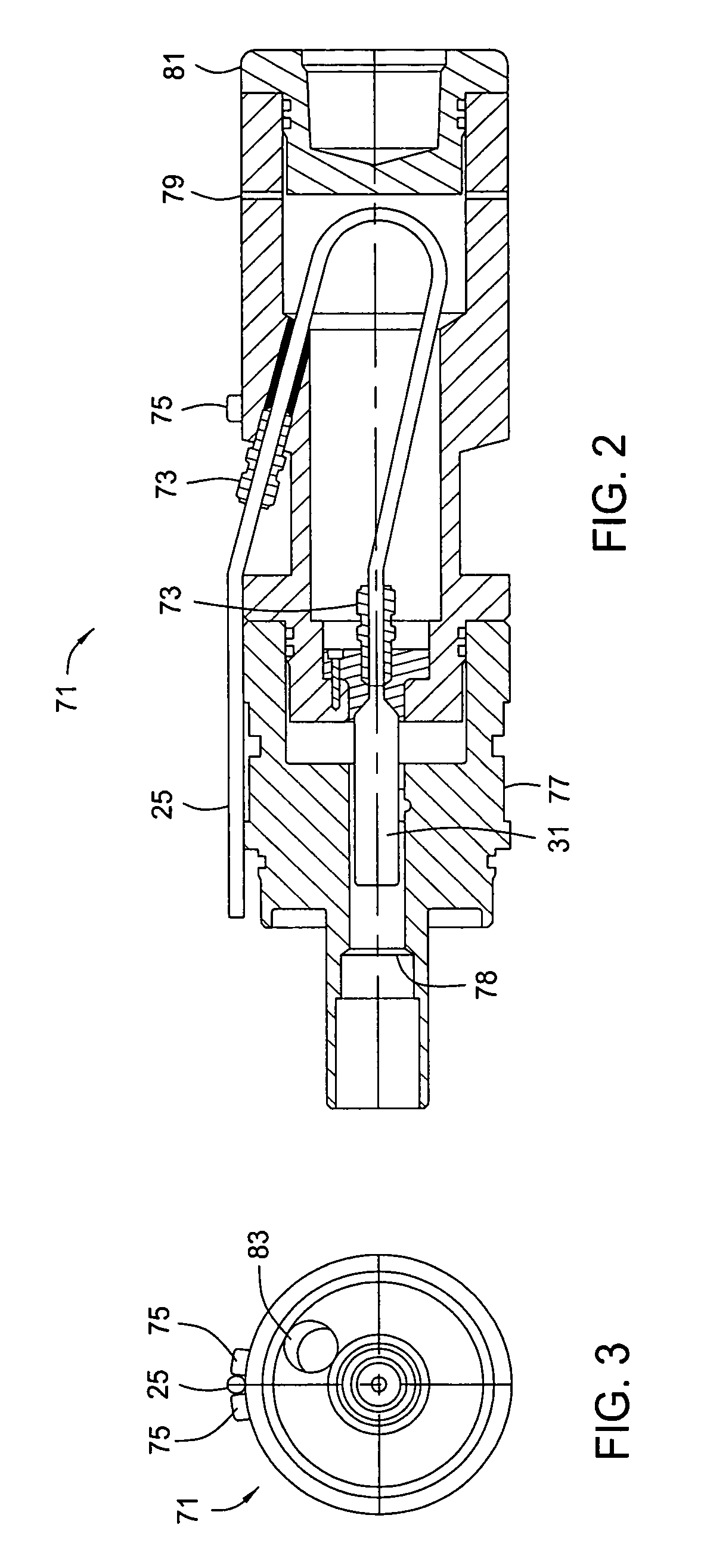
[0022]Referring to FIG. 1, one embodiment of a system, method, and apparatus for providing fiber optic communications for a downhole submersible pump assembly is disclosed. The invention comprises a downhole submersible pump 11, such as a jet pump, an electrical submersible pump (ESP) having a motor, rod lift or driven pumps, gas lift pumps, or other types of pump assemblies that may be located in a well 13 on a string of tubing 15. The fiber optic system includes a surface panel 21 at the ground surface 23 of the well 13 that provides a laser light source and control of the fiber optic system. A fiber optic cable 25 extends from the surface panel 21 to the pump 11. The invention also incorporates fiber optic temperature and pressure sensors 31, at least some of which are located below the pump 11 for monitoring temperature and pressure in the well 13.

[0023]There are many different types of fiber optic temperature and pressure sensors that may be employed with the invention. For exa...


PUM


Abstract

A downhole submersible pump system, method, and apparatus utilizes fiber optic sensors and distributed temperature sensors below the submersible pump to monitor pump discharge pressure and temperature, intake pressure and temperature, and motor temperature. In addition, distributed temperature sensors are used below the pump to monitor the perforations within the well bore.

Description

BACKGROUND OF THE INVENTION[0001]1. Technical Field[0002]The present invention relates in general to downhole submersible pumps and, in particular, to an improved system, method, and apparatus for a downhole electrical submersible pump equipped with a fiber optic communications.[0003]2. Description of the Related Art[0004]Many different techniques have been used to monitor well bores during completion and production of well bores, reservoir conditions, estimating quantities of hydrocarbons, operating downhole devices in the well bores, and determining the physical condition of the well bore and downhole devices. Reservoir monitoring involves determining certain downhole parameters in producing well bores at various locations in one or more producing well bores in a field, typically over extended time periods.[0005]Wire line tools are commonly used to obtain such measurements, which involves transporting the wire line tools to the well site, conveying the tools into the well bores, s...

Claims


Application Information

Patent Timeline
Patent Type & Authority Patents(United States)
IPC IPC(8): E21B47/06
CPCE21B47/123E21B43/126E21B47/135E21B43/128
Inventor MCCOY, ROBERTBESSER, GORDONREYNOLDS, ALAN
Owner BAKER HUGHES INC
Why Eureka
Try Eureka